
Motor Series
CONTACT Us
- TEL: 0086-532- 66736879
- FAX: 0086-532- 66736879
- E-MAIL: marketing@sdljdj.com
- ADD: No.22,Shanhai Road, Rushan City, Shandong, China
 High Efficiency Three Phase Asynchronous Electric Motor Dedicated for Compressor")
Center Height of Frame: H80~H355mm
Rated Output Power: 0. 75kW~315kW
Rated Voltage: 380V,50Hz
(can be customized)
Grade of Protections: IP55
Class of Insulation: F
Cooling Type: IC411


 Share
Share
Outlines
KYGL Series Dedicated for Compressor High Efficiency Three Phase Induction Motor is specialized developed and designed according to features of air compressor, can meet requirement of irregular shot-time over load for compressor and has complete enclosure structure, self-cooling and squirrel case. It has advantages of high efficiency, high torque, good starting performance, low noise, small vibration and safe operation. Its power grade and mounting size conform to international IEC standard.
The service factor for frame H80-H180 is 1.2,and 1.15 for frame H200-H355. It can work normally at ambient temperature below 46℃.
Technical Data of KYGJ Series
|
Type |
Rated Power (kW) |
EFF η(%) |
Power Factor (cosφ) |
Rated Current (A) |
Locked Torque Rated Torque |
Min Torque Rated Torque |
Max Torque Rated Torque |
Locked Current Rated Current |
Service Factor |
|
2Poles—3000rpm Synchronous speed 50Hz |
|||||||||
|
KYGJ80M1-2 |
0.75 |
77.4 |
0.82 |
1.80 |
2.3 |
1.5 |
2.6 |
7.3 |
1.2 |
|
KYGJ80M2-2 |
1.1 |
79.6 |
0.83 |
2.53 |
|||||
|
KYGJ90S-2 |
1.5 |
81.3 |
0.84 |
3.34 |
|||||
|
KYGJ90L-2 |
2.2 |
83.2 |
0.85 |
4.73 |
1.4 |
7.5 |
|||
|
KYGJ100L-2 |
3 |
84.6 |
0.86 |
6.26 |
|||||
|
KYGJ112M-2 |
4 |
85.8 |
0.87 |
8.14 |
|||||
|
KYGJ132S1-2 |
5.5 |
87.0 |
0.87 |
11.0 |
1.2 |
||||
|
KYGJ132S2-2 |
7.5 |
88.1 |
0.88 |
14.7 |
|||||
|
KYGJ160M1-2 |
11 |
89.4 |
0.88 |
21.2 |
|||||
|
KYGJ160M2-2 |
15 |
90.3 |
0.88 |
28.7 |
|||||
|
KYGJ160L-2 |
18.5 |
90.9 |
0.88 |
35.1 |
1.1 |
||||
|
KYGJ180M-2 |
22 |
91.3 |
0.88 |
41.6 |
|||||
|
KYGJ200L1-2 |
30 |
92.0 |
0.89 |
55.7 |
2.2 |
7.4 |
1.15 |
||
|
KYGJ200L2-2 |
37 |
92.5 |
0.89 |
68.3 |
|||||
|
KYGJ225M-2 |
45 |
92.9 |
0.89 |
82.7 |
1.0 |
||||
|
KYGJ250M-2 |
55 |
93.2 |
0.89 |
100.7 |
|||||
|
KYGJ280S-2 |
75 |
93.8 |
0.89 |
136.5 |
2.0 |
0.9 |
6.9 |
||
|
KYGJ280M-2 |
90 |
94.1 |
0.89 |
163.3 |
7.0 |
||||
|
KYGJ315S-2 |
110 |
94.3 |
0.90 |
196.9 |
2.5 |
||||
|
KYGJ315M-2 |
132 |
94.6 |
0.90 |
235.6 |
|||||
|
KYGJ315L1-2 |
160 |
94.8 |
0.90 |
284.9 |
|||||
|
KYGJ315L2-2 |
185 |
95.0 |
0.90 |
328.8 |
0.8 |
7.1 |
|||
|
KYGJ315L3-2 |
200 |
95.0 |
0.90 |
355.4 |
|||||
|
KYGJ355M-2 |
200 |
95.0 |
0.90 |
355.4 |
1.9 |
||||
|
KYGJ355L1-2 |
250 |
95.0 |
0.90 |
444.3 |
|||||
|
KYGJ355L2-2 |
280 |
95.0 |
0.90 |
497.6 |
|||||
|
KYGJ355L3-2 |
315 |
95.0 |
0.90 |
559.8 |
|||||
|
Type |
Power (kW) |
EFF η(%) |
Power Factor (cosφ) |
Rated Current (A) |
Locked Torque Rated Torque |
Min Torque Rated Torque |
Max Torque Rated Torque |
Locked Current Rated Current |
Service Factor |
|
4Poles—1500rpm Synchronous speed 50Hz |
|||||||||
|
KYGJ80M-4 |
0.75 |
79.6 |
0.76 |
1.88 |
2.3 |
1.6 |
2.6 |
7.0 |
1.2 |
|
KYGJ90S-4 |
1.1 |
81.4 |
0.77 |
2.67 |
|||||
|
KYGJ90L-4 |
1.5 |
82.8 |
0.78 |
3.53 |
|||||
|
KYGJ100L1-4 |
2.2 |
84.3 |
0.80 |
4.96 |
1.5 |
7.3 |
|||
|
KYGJ100L2-4 |
3 |
85.5 |
0.81 |
6.58 |
|||||
|
KYGJ112M-4 |
4 |
86.6 |
0.81 |
8.66 |
|||||
|
KYGJ132S-4 |
5.5 |
87.7 |
0.82 |
11.6 |
2.2 |
1.4 |
|||
|
KYGJ132M-4 |
7.5 |
88.7 |
0.83 |
15.5 |
|||||
|
KYGJ160M-4 |
11 |
89.8 |
0.83 |
22.4 |
|||||
|
KYGJ160L-4 |
15 |
90.6 |
0.84 |
29.9 |
|||||
|
KYGJ180M-4 |
18.5 |
91.2 |
0.85 |
36.3 |
1.2 |
||||
|
KYGJ180L-4 |
22 |
91.6 |
0.85 |
42.9 |
|||||
|
KYGJ200L-4 |
30 |
92.3 |
0.85 |
58.1 |
7.2 |
1.15 |
|||
|
KYGJ225S-4 |
37 |
92.7 |
0.86 |
70.5 |
|||||
|
KYGJ225M-4 |
45 |
93.1 |
0.86 |
85.4 |
1.1 |
||||
|
KYGJ250M-4 |
55 |
93.5 |
0.86 |
103.9 |
|||||
|
KYGJ280S-4 |
75 |
94.0 |
0.87 |
139.3 |
1.0 |
6.8 |
|||
|
KYGJ280M-4 |
90 |
94.2 |
0.87 |
166.9 |
6.9 |
||||
|
KYGJ315S-4 |
110 |
94.5 |
0.88 |
201.0 |
2.1 |
2.5 |
|||
|
KYGJ315M-4 |
132 |
94.7 |
0.88 |
240.7 |
|||||
|
KYGJ315L1-4 |
160 |
94.9 |
0.89 |
287.8 |
7.0 |
||||
|
KYGJ315L2-4 |
185 |
95.1 |
0.89 |
332.1 |
0.9 |
||||
|
KYGJ315L3-4 |
200 |
95.1 |
0.89 |
359.0 |
|||||
|
KYGJ355M-4 |
220 |
95.1 |
0.89 |
394.9 |
|||||
|
KYGJ355L1-4 |
250 |
95.1 |
0.89 |
448.8 |
|||||
|
KYGJ355L2-4 |
280 |
95.1 |
0.89 |
502.6 |
0.8 |
||||
|
KYGJ355L3-4 |
315 |
95.1 |
0.89 |
565.5 |
|||||
Outline and Mounting Dimensions
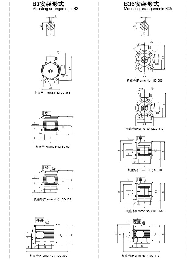
|
Frame No. |
Poles |
Mounting Dimensions |
Outline Dimensions |
||||||||||||||||||||||||||||||||
|
A |
A/2 |
B |
C |
D |
E |
F |
G |
H |
K |
M |
N |
P |
R |
S |
T |
Holes of Flange . |
AB |
AC |
AD |
HD |
L |
||||||||||||||
|
80M |
2.4 |
125 |
62.5 |
100 |
50 |
±1.5 |
19 |
+0.009 -0.004 |
40 |
±0.31 |
6 |
0 -0.030 |
15.5 |
0 -0.10 |
80 |
0 -0.5 |
10 |
+0.36 0 |
165 |
130 |
+0.014 -0.011 |
200 |
0 |
±1.5 |
12 |
+0.43 0 |
φ1.0 M |
3.5 |
0 -0.12 |
4 |
165 |
175 |
145 |
175 |
350 |
|
90S |
2.4 |
140 |
70 |
56 |
24 |
50 |
8 |
0 -0.036 |
20 |
0 -0.20 |
90 |
180 |
195 |
155 |
195 |
390 |
|||||||||||||||||||
|
90L |
125 |
410 |
|||||||||||||||||||||||||||||||||
|
100L |
160 |
80 |
140 |
63 |
±2.0 |
28 |
60 |
±0.37 |
24 |
100 |
12 |
+0.43 0 |
215 |
180 |
250 |
±2.0 |
14.5 |
φ1.2 M |
4 |
205 |
215 |
180 |
245 |
455 |
|||||||||||
|
112M |
190 |
95 |
70 |
112 |
245 |
240 |
190 |
265 |
480 |
||||||||||||||||||||||||||
|
132S |
2.4 |
216 |
108 |
89 |
38 |
+0.018 +0.002 |
80 |
10 |
33 |
132 |
265 |
230 |
+0.016 -0.013 |
300 |
280 |
275 |
210 |
315 |
530 |
||||||||||||||||
|
132M |
178 |
570 |
|||||||||||||||||||||||||||||||||
|
160M |
254 |
127 |
210 |
108 |
±3.0 |
42 |
110 |
±0.43 |
12 |
0 -0.043
|
37 |
160 |
14.5 |
300 |
250 |
350 |
±3.0 |
18.5 |
+0.52 0 |
5 |
330 |
335 |
265 |
385 |
655 |
||||||||||
|
160L |
254 |
700 |
|||||||||||||||||||||||||||||||||
|
180M |
279 |
139.5 |
241 |
121 |
48 |
14 |
42.5 |
180 |
355 |
380 |
285 |
430 |
725 |
||||||||||||||||||||||
|
180L |
279 |
765 |
|||||||||||||||||||||||||||||||||
|
200L |
318 |
159 |
305 |
133 |
55 |
+0.030 +0.011 |
16 |
49 |
200 |
18.5 |
+0.52 0 |
350 |
300 |
±0.016 |
400 |
395 |
420 |
315 |
475 |
850 |
|||||||||||||||
|
225S |
4 |
356 |
406 |
286 |
149 |
±4.0 |
60 |
140 |
±0.50 |
18 |
53 |
225 |
400 |
350 |
±0.018 |
450 |
±4.0 |
8 |
435 |
475 |
345 |
530 |
900 |
||||||||||||
|
225M |
2 |
311 |
55 |
110 |
±0.43 |
16 |
49 |
915 |
|||||||||||||||||||||||||||
|
4 |
60 |
140 |
±0.50 |
18 |
53 |
930 |
|||||||||||||||||||||||||||||
|
250M |
2 |
406 |
203 |
349 |
168 |
±4.0 |
250 |
24 |
500 |
450 |
±0.020 |
550 |
490 |
515 |
385 |
575 |
1015 |
||||||||||||||||||
|
4 |
65 |
58 |
|||||||||||||||||||||||||||||||||
|
280S |
2 |
457 |
228.5 |
368 |
190 |
280 |
0 -1.0 |
550 |
580 |
410 |
640 |
1130 |
|||||||||||||||||||||||
|
4 |
75 |
20 |
0 -0.052 |
67.5 |
|||||||||||||||||||||||||||||||
|
280M |
2 |
419 |
65 |
18 |
0 -0.043 |
58 |
1180 |
||||||||||||||||||||||||||||
|
4 |
75 |
20 |
0 -0.052 |
67.5 |
|||||||||||||||||||||||||||||||
|
315S |
2 |
508 |
254 |
406 |
216 |
65 |
18 |
0 -0.043 |
58 |
315 |
28 |
600 |
550 |
±0.022 |
660 |
24 |
Φ2.0 M |
6 |
0 -0.15 |
8 |
635 |
645 |
576 |
865 |
1340 |
||||||||||
|
4 |
80 |
170 |
22 |
0 -0.052 |
71 |
1370 |
|||||||||||||||||||||||||||||
|
315M |
2 |
457 |
65 |
140 |
18 |
0 -0.043 |
58 |
1410 |
|||||||||||||||||||||||||||
|
4 |
80 |
170 |
22 |
0 -0.052 |
71 |
1455 |
|||||||||||||||||||||||||||||
|
315L |
2 |
508 |
65 |
140 |
18 |
0 -0.043 |
58 |
1410 |
|||||||||||||||||||||||||||
|
4 |
80 |
170 |
22 |
0 -0.052 |
71 |
1455 |
|||||||||||||||||||||||||||||
|
355M |
2 |
610 |
305 |
560 |
254 |
4.0 |
75 |
140 |
20 |
67.5 |
355 |
740 |
680 |
±0.025 |
800 |
740 |
750 |
680 |
1035 |
1640 |
|||||||||||||||
|
4 |
95 |
+0.033 +0.013 |
170 |
25 |
86 |
1670 |
|||||||||||||||||||||||||||||
|
355L |
2 |
630 |
75 |
+0.033 +0.013 |
140 |
20 |
67.5 |
1640 |
|||||||||||||||||||||||||||
|
4 |
95 |
+0.033 +0.013 |
170 |
25 |
86 |
1670 |
|||||||||||||||||||||||||||||
Note: Size R is the distance between the flange fitting surface and the shaft shoulder.
Have any Queries? Let us know. We will clear it for you at the best.


