
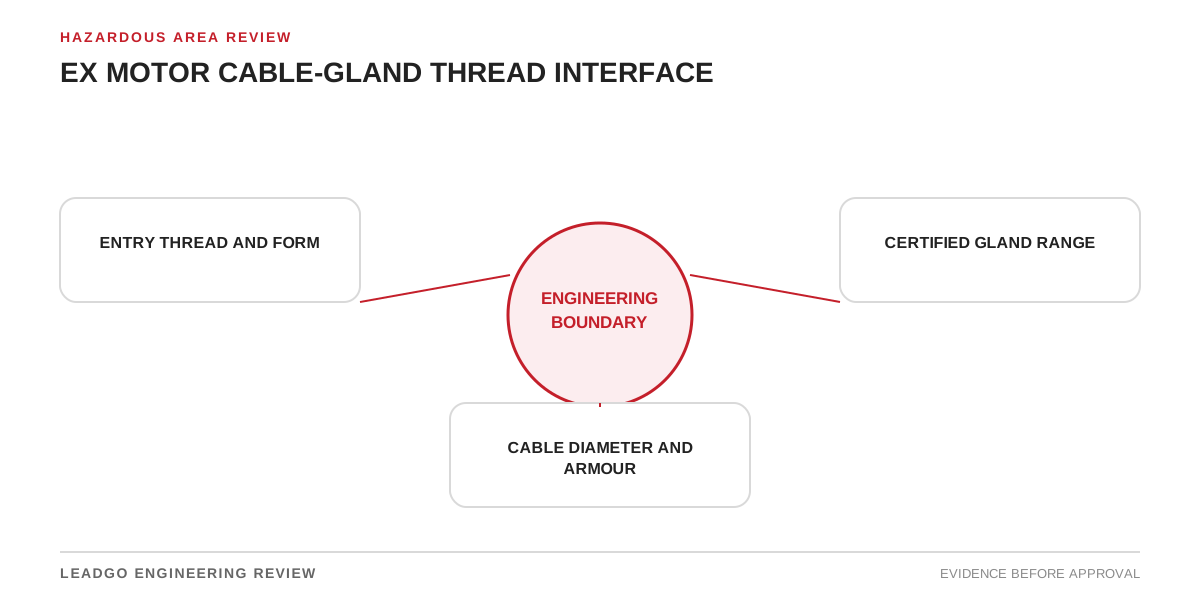
The cable gland is not a loose accessory added after motor selection. In a hazardous area, the motor entry, gland, cable and installation method form one protection interface. A matching nominal thread does not prove that the gland is certified for the protection concept, cable construction, ambient condition or sealing arrangement.
This interface often sits between procurement packages. The motor supplier knows the terminal-box entry; the electrical contractor selects cable; another party purchases glands. Unless the RFQ assigns data and approval responsibility, incompatibility may appear only during installation.
Boundaries of the Ex entry review
This review applies to hazardous-area motors with direct cable entries or terminal boxes using certified glands, stopping plugs, adaptors or reducers. It supports projects using armoured, unarmoured, braided or screened cable, subject to the governing area classification and installation rules.
It is not a universal gland-selection table. Protection concept, gas or dust group, equipment protection level, temperature class, ambient range, ingress protection and local code requirements must come from the project and certificates. Installation must follow the exact manufacturer instructions for the supplied motor, gland and cable.
Engineering tool: cable-entry compatibility matrix
| Interface field | Motor evidence | Gland and cable evidence | Acceptance question |
|---|---|---|---|
| Area basis | Equipment marking and certificate scope | Gland marking and certificate scope | Do all items suit the classified location? |
| Protection concept | Terminal-box protection and instructions | Gland protection method | Is the gland permitted for that concept? |
| Entry thread | Drawing, certificate schedule or instructions | Certified thread designation | Are form, size, pitch and engagement compatible? |
| Adaptor or reducer | Permitted arrangement and entry limits | Accessory certificate and instructions | Is every added component approved in the chain? |
| Cable construction | Terminal and earthing arrangement | Armoured, unarmoured, braid or screen details | Can the gland terminate the actual cable correctly? |
| Cable diameter | Entry space and layout | Certified outer and bedding diameter range | Does the purchased cable fall inside the gland range? |
| Sealing | Motor protection requirements | Barrier, compression seal or compound instructions | Is the required sealing method defined and installable? |
| Armour termination | Earthing and bonding design | Armour size and clamping range | Is mechanical retention and earth continuity adequate? |
| Environmental duty | Ambient and ingress requirements | Material, seals and ingress rating | Are corrosion, temperature and water exposure covered? |
| Installation space | Terminal-box geometry and access | Gland body, locknut and bend radius | Can it be assembled and inspected without interference? |
| Unused entries | Number and thread of spare holes | Certified stopping-plug details | Are unused openings closed by suitable devices? |
| Final evidence | Nameplate, drawing and inspection plan | Certificates, instructions and inspection record | Can the installed combination be traced and inspected? |
Complete the matrix for every entry type, not merely one representative hole. Main power, heaters, winding sensors, bearing sensors and encoders may use different cables and glands.
Ten-step entry-system selection route
- Freeze the hazardous-area classification and governing installation basis.
- Obtain the motor marking, certificate with schedules and manufacturer instructions.
- List every terminal-box entry, thread form, size, location and intended circuit.
- Obtain actual cable construction, armour or screen, outer diameter and inner bedding diameter where relevant.
- Select a gland whose certificate and instructions cover the protection concept and cable.
- Check adaptors, reducers, stopping plugs and washers as certified components where required.
- Review earthing, bonding, armour termination and screen treatment.
- Confirm physical access, cable bend, gland spacing and terminal clearances.
- Put installation checks into the inspection plan.
- Retain certificates, instructions and installed-entry records in the final dossier.
Thread details that must not be guessed
Record the full thread designation, not “metric” or “NPT” alone. Form, nominal size, pitch or threads per unit length, taper or parallel construction, engagement and sealing method matter. Visual similarity is unreliable. For parallel threads, the required sealing and locking arrangement may differ from tapered threads.
Do not machine, chase or enlarge an Ex entry in the field unless the certificate holder and approved procedure explicitly permit the work. A mechanically successful fit can still invalidate the protection basis.
Cable construction controls gland choice
The cable schedule should identify more than conductor size. The gland may need the overall diameter, bedding diameter, armour type and dimensions, sheath material, screen or braid arrangement and whether the cable can transmit gas through its construction under the applicable installation rules.
Terminal space also matters. Large conductors, stress control, lugs and bend radius can make a certified gland impossible to install in the selected entry. Review the cable route and box orientation before manufacturing release rather than adding adaptors at site to recover space.
Common interface errors that certification files do not cure
Selecting by catalogue thread size alone is the most common shortcut. Another is assuming the motor’s hazardous-area certificate automatically covers any certified gland. Each item may be certified, yet their protection concepts, ambient limits or installation conditions may not align.
Projects also leave gland supply to the contractor without transmitting motor-entry data, or order glands before the final cable manufacturer confirms diameters. Nominal cable size does not guarantee sheath dimensions.
Using multiple adaptors to solve a mismatch increases interfaces and can create space, bonding and inspection problems. Unused entries are sometimes closed with ordinary plugs. Stopping devices must suit the applicable protection and entry arrangement.
Finally, a certificate file alone does not prove correct installation. Incorrect strip length, damaged seals, poor armour capture, missing earth continuity or inadequate tightening can defeat a compatible design.
Motor-supplier interface data required at RFQ stage
Ask for the complete motor certificate and schedules, marking, terminal-box protection concept, entry drawing, full thread designations, quantity and location of entries, permitted adaptors or stopping devices, ambient limits, earthing points, terminal-box dimensions and manufacturer installation instructions.
Request a responsibility statement for glands: supplied loose, installed at factory or excluded. If installed, require the gland make and model, certificate, cable range, installation record and treatment of unused entries. If excluded, require sufficient controlled data for the buyer’s selected gland to be reviewed before shipment.
Installation and acceptance evidence
The final inspection should compare installed gland markings with the approved schedule; verify cable diameter and construction against the certified range; confirm thread and accessory arrangement; inspect seals, armour capture, bonding, earthing and unused entries; and check that the cable is supported without loading the gland or terminals.
Photographs can support the record but should not replace hands-on inspection required by the project. Retain the cable schedule, entry matrix, certificates, instructions, approved deviations and inspection results together. That package allows future maintenance teams to replace a gland or cable without rebuilding the original selection logic from fragments.
Inspection planning should distinguish initial detailed inspection from routine visual checks and maintenance intervention. Any time a gland is disturbed, replaced or moved to another cable, reassess the certified range, seals, armour termination and tightening instructions. Do not assume that a previously accepted gland remains suitable after cable replacement simply because the thread still fits.
RFQ boundary
State who supplies and installs each gland, who approves the cable-entry matrix, when final cable data is due, whether spare entries are required and what evidence must be included in the motor data book. A clear interface at RFQ stage costs less than changing terminal boxes, cables or certified accessories during commissioning.
Add a release condition that final cable data and gland selection must be approved before the terminal box is frozen where entry size or layout may change. If the contractor is not yet appointed, define bounding cable assumptions and require later verification. The boundary should also state who owns any adaptor introduced to reconcile the final cable with the manufactured entry.