
Long motor leads can produce a terminal-voltage peak that is not visible in an ordinary RMS reading. Measuring it requires a planned high-voltage test; an improvised oscilloscope connection can be unsafe and can also create a false waveform.
Define the measurement objective
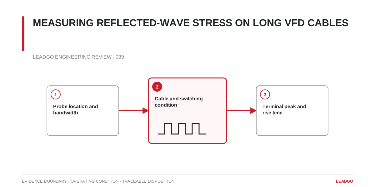
Decide whether the test is checking peak line-to-line voltage, rise time, ringing frequency or filter performance. The probe, bandwidth and sample settings must suit that objective. Follow the instrument and drive manufacturers’ safety procedures, isolation requirements and connection limits.
Measure at the motor terminals when the purpose is to assess motor insulation stress. A drive-terminal trace is useful as a reference but cannot replace the receiving-end measurement.
Preserve the installation condition
Document cable construction, length, shielding, grounding, routing and any output reactor, dV/dt filter or sine-wave filter. Record DC-bus voltage, carrier frequency, modulation mode and motor load. Changing any of these can change the observed peak.
Avoid long probe leads and uncontrolled ground loops. Measurement wiring should be short, secure and arranged so it does not alter clearances or contact moving parts. Only qualified personnel should perform the energized test.
Waveform acceptance decision
Capture repeated switching events under the credible maximum DC-bus condition. The disposition should confirm:
- peak magnitude against the specified motor-terminal limit;
- rise time against the insulation and filter basis;
- repeatability across representative switching events.
A single unusual pulse should be investigated, not automatically treated as the normal envelope.
If mitigation is required, verify the selected device at the motor terminals after installation. Retain before-and-after traces with time and voltage scales visible.