
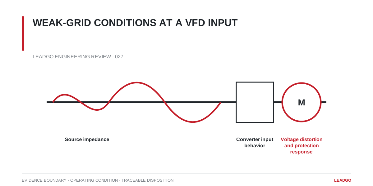
A drive that performs normally on a strong factory bus can nuisance-trip or distort its supply when connected through a long feeder, small transformer or isolated generator. The motor may be healthy; the unstable interface is at the VFD input.
Define the connection point
Collect the upstream transformer rating and impedance, feeder length and size, available short-circuit current, normal voltage range and operating configurations. Include generators, switched capacitor banks and other large drives that can change the source condition.
Use the minimum credible short-circuit strength, not only the normal utility case. Maintenance switching or generator operation may create the limiting condition.
Separate the symptoms
Repeated undervoltage trips can come from steady voltage drop, a short process transient or a control setting. DC-bus overvoltage may be associated with regeneration on the motor side rather than a weak input. Harmonic distortion, commutation notches and voltage unbalance require different evidence.
A useful study compares:
- source impedance and available fault level;
- VFD input-current spectrum and loading;
- transformer and cable thermal duty;
- point-of-common-coupling voltage distortion;
- capacitor or filter resonance;
- voltage dip and recovery during major load changes.
Mitigation selection decision
An input reactor, DC choke, active front end or harmonic filter changes both current and voltage behavior. Do not add equipment from a generic rule without checking voltage drop, resonance and control compatibility.
Commissioning should capture supply voltage, current, DC-bus behavior and event logs during the weak-grid case. Retain the one-line diagram and study assumptions so a future network change can be assessed against the same baseline.