
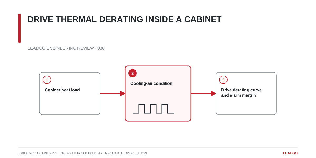
A VFD can be correctly sized by current and still operate too close to its thermal limit. The common gap is between the room condition in the specification and the cooling air that actually reaches the drive inside a working cabinet.
Calculate the enclosure heat load
List losses from the drive, reactors, harmonic filters, braking components, power supplies and transformers. Use manufacturer loss data at the expected operating point instead of applying an arbitrary percentage to nameplate power.
Define the worst credible combination of load, carrier frequency, ambient temperature and equipment availability. An intermittent duty still needs a time-based check; a daily average can hide a peak that causes an overtemperature trip.
Trace the airflow
Review where air enters, what it passes first and whether hot discharge returns to the inlet. Cable bundles, gland plates and partitions can create a hot pocket even when total fan flow appears adequate. For filtered ventilation, include pressure loss with a realistically loaded filter.
| Check | Evidence |
|---|---|
| Drive loss at duty | Manufacturer loss data |
| Inlet temperature limit | Drive manual and derating curve |
| Heat removal | Ventilation or cooling calculation |
| Air-path separation | Cabinet layout and fan direction |
| Site condition | Maximum ambient, altitude and contamination |
Temperature, altitude, carrier frequency and enclosure type may all reduce capacity. Confirm how the manufacturer combines them.
During commissioning, measure at the drive inlet, not the cabinet door. Trend temperature with load until stable, and retain the heat calculation, settings and readings in the acceptance file.