
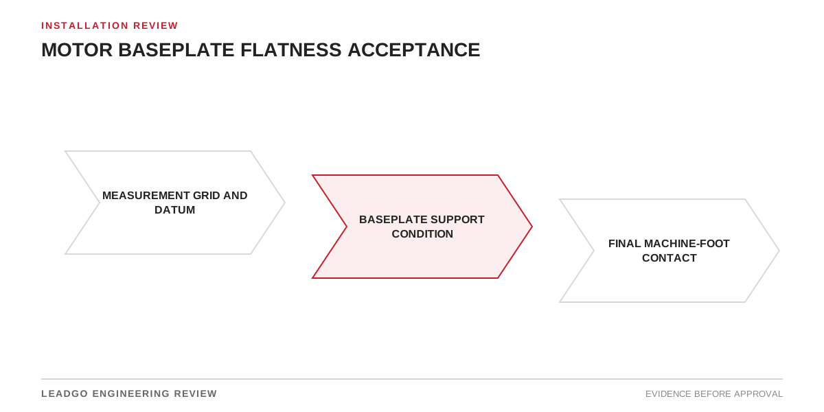
A straightedge reading taken on an unloaded fabrication does not prove that the installed machine will sit without distortion. Welding, transport, foundation contact, grout, anchor bolts and connected equipment can all change the condition seen at the motor feet.
State the measurement stage
| Stage | What the record should state | Decision supported |
|---|---|---|
| Fabrication | Datum, grid, surface preparation and unsupported or supported condition | Release for machining or shipment |
| Foundation set | Support points, anchor condition and preliminary level | Readiness for grouting |
| After grout cure | Datum repeated, void or support findings and bolt state | Readiness for machine placement |
| Motor placement | Foot-contact or soft-foot result before forced tightening | Shim and correction plan |
| Final alignment | Bolt torque state, piping/coupling influence and hot-alignment assumptions | Mechanical release for commissioning |
Each result should include instrument identification and the location of every reading. A maximum value without a map cannot show whether the issue is a local high point, a twisted support or a general slope.
Do not force the motor to fit
Clean mating surfaces and confirm that paint, burrs or debris are not controlling the reading. Check individual foot contact before using bolt force to pull the frame down. If tightening changes alignment or foot readings materially, investigate the support rather than adding undocumented shims.
Connected piping, belt load and coupling forces belong in the final condition review. A baseplate can measure correctly before these interfaces are applied and still distort afterwards.
Release criteria that remain auditable
- The drawing or installation procedure identifies the datum and acceptance source.
- The measurement grid covers every motor support region.
- Corrections and shim packs are identified by location and retained with the alignment record.
- Final readings use the documented bolt and support condition.
- Deviations have an engineering disposition rather than a verbal acceptance.
Flatness supports alignment but does not replace it. Review the shaft interface in Motor Shaft Dimensions and Coupling Fit and the mounting arrangement in B3, B5, B35 and V1 Motor Mountings.