
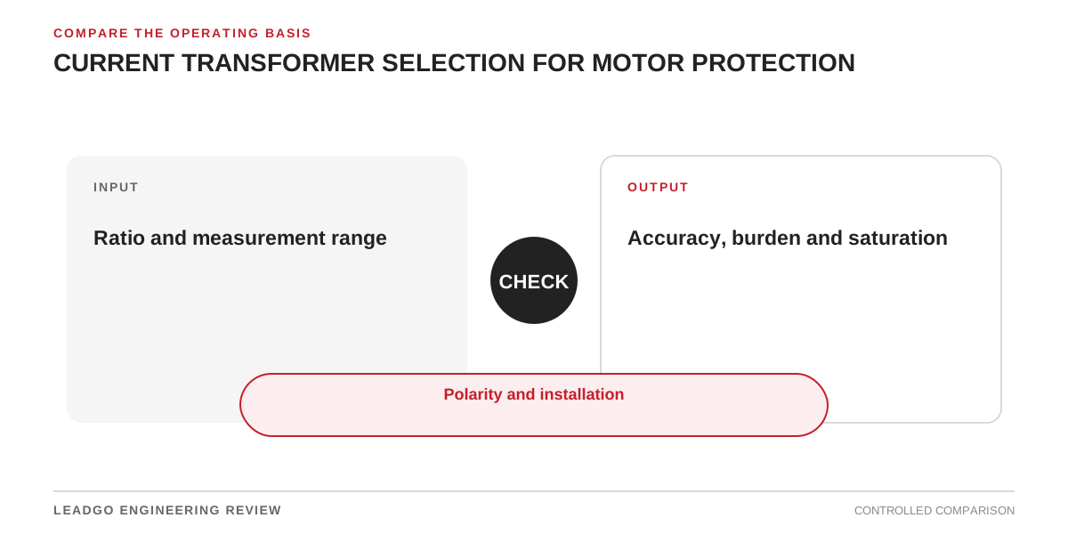
The same CT must support normal measurement, motor starting and protection during abnormal current. Oversizing for fault current can sacrifice sensitivity; undersizing can lead to saturation.
| Input | Check | Evidence |
|---|---|---|
| Rated/load current | Relay measurement range | Load study and nameplate |
| Starting current/time | Transient reproduction and relay restraint | Motor curve/start study |
| Fault current/X-R | Saturation performance | Short-circuit study |
| Secondary burden | CT accuracy capability | Lead and relay burden calculation |
Close installation details
Confirm polarity, phase assignment, core use, secondary grounding point, terminal shorting provisions and safe maintenance practice. Differential schemes also require matched location and zone boundaries.
Commission with ratio/polarity checks, secondary injection as applicable and end-to-end verification of displayed current and relay logic. Store the CT datasheet, excitation information, burden calculation and final settings together.
Related reading: motor protection basics and starting-current calculation.