
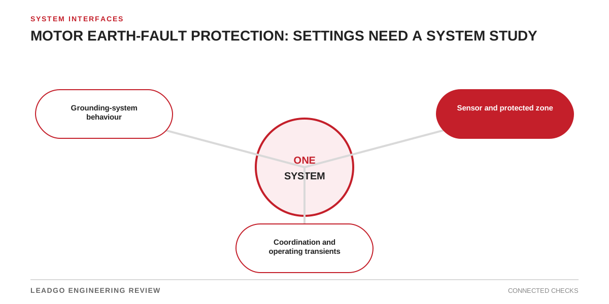
Earth-fault protection is a system decision. The motor rating identifies the protected asset, but it does not define the available ground-fault current or what the relay measures. Those depend on the network neutral, cable circuit and current-transformer arrangement.
Draw the current path before entering a setting
Begin with the single-line diagram and mark every conductor that can carry earth-fault current. Include the transformer or generator neutral, grounding resistor or reactor, feeder cable screens, parallel earth paths and the motor frame connection. Then draw the measurement boundary around the CTs.
This exercise identifies which faults are inside the protected zone and which healthy-system currents may appear at the relay input.
| System and sensor arrangement | What the relay observes | Review point before choosing pickup or delay |
|---|---|---|
| Residual sum of three phase CTs | Vector sum of phase-secondary currents | CT ratio, class, saturation and mismatch during motor starting or external faults |
| Core-balance CT around all phase conductors | Net primary current through one core | All phase conductors must pass through the core consistently; screen and earth conductors need an intentional routing decision |
| Neutral CT on a grounded machine or source neutral | Current in that neutral connection | The protected winding zone and alternative earth-current paths must be explicit |
| Restricted earth-fault or machine differential scheme | Difference within a defined CT boundary | CT location, polarity, stabilisation method and minimum fault coverage govern performance |
| Directional earth-fault element | Residual current interpreted with a polarising quantity | Grounding arrangement and polarising voltage or current quality must support directionality |
ABB’s motor-protection guidance lists several of these functions for stator short circuits and earth faults. The distinction prevents a common specification error: treating every element carrying an earth-fault label as the same protection.
Sensitivity and security pull in opposite directions
A lower pickup can detect a smaller internal fault, but it also reduces margin against CT spill current, cable charging current, converter-related common-mode current and measurement noise. A longer delay may improve coordination, yet it increases fault exposure. The acceptable balance comes from the grounding and protection-coordination studies, not a generic percentage of motor full-load current.
For resistance-grounded systems, use the actual resistor data and operating configuration. For solidly grounded systems, include source and feeder impedance. If the plant can run with alternative neutrals or bus ties, assess each permitted state.
Installation details are protection inputs
Core-balance CT performance can be defeated by inconsistent cable-screen routing. Phase-CT residual summation can show spill current when separate CTs do not reproduce large starting or through-fault currents equally. Neither issue is resolved by raising pickup until nuisance trips stop.
The cable termination drawing, CT datasheet and relay wiring diagram belong in the same package as the setting calculation. Commissioning should verify polarity, ratio, input scaling and the trip path before energisation.
Approval record
Approve the setting only when the file identifies:
- every normal grounding configuration;
- maximum and minimum earth-fault current for the protected zone;
- CT type, ratio, class, location and conductor routing;
- expected residual current during starting and converter operation, where applicable;
- upstream and downstream grading requirements;
- injection-test values and the accepted trip logic.
If one item remains provisional, label the setting provisional as well. A relay value without its system basis is not a completed protection design.