
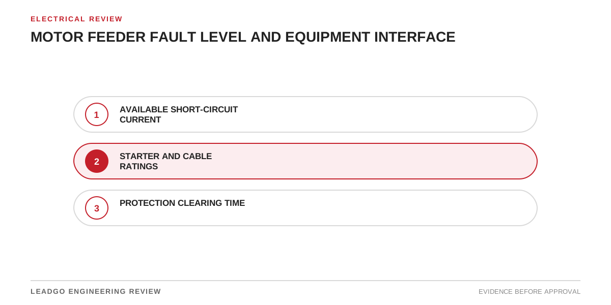
“Fault level at the bus” is not yet a motor-feeder approval. The study must identify fault location, operating configuration, source contribution and voltage basis, then connect those results to each installed component and the protective device that clears the fault.
One interface register for the feeder
| Item | Rating or behaviour to verify | Required project input |
|---|---|---|
| Switchgear and starter | Breaking, making and short-time duty; coordination type where applicable | Maximum fault case and device combination |
| Contactor or bypass path | Conditional short-circuit rating and backup protection | Manufacturer-tested combination |
| VFD or soft starter | Input protection and short-circuit coordination instructions | Approved device manual and fuse/breaker selection |
| Power cable | Thermal withstand and installation condition | Fault current, clearing time, conductor data |
| Motor terminal box and accessories | Applicable withstand and protective arrangement | Motor documentation and feeder design |
| CTs and relays | Measurement range, saturation risk and operating time | Maximum and minimum fault cases |
| Grounding path | Fault return path and touch-voltage design interface | Earthing study and installation drawings |
Do not mix a maximum fault current from one network arrangement with a clearing time calculated for another. Tie every result to the study revision and operating case.
Review both ends of protection performance
The maximum-fault case tests equipment duty. The minimum-fault case helps show whether protection will detect and clear the event as intended. Motor starting current, transformer energisation and VFD behaviour also matter because settings must remain secure during normal transients.
Where current-limiting devices are credited, use the manufacturer’s tested coordination data and the exact combination. A component’s standalone rating does not prove the assembled feeder rating.
Release conditions
- Study revision and single-line diagram agree.
- Every component has a traceable rating or tested combination.
- Cable thermal check uses the coordinated clearing time.
- Settings, CT ratios and trip logic match the approved study.
- Changes to source, transformer, generator or operating configuration trigger review.
For starting-system selection, see DOL, Star-Delta, Soft Starter or VFD. Keep fault coordination separate from the motor overload function while checking their interfaces.