
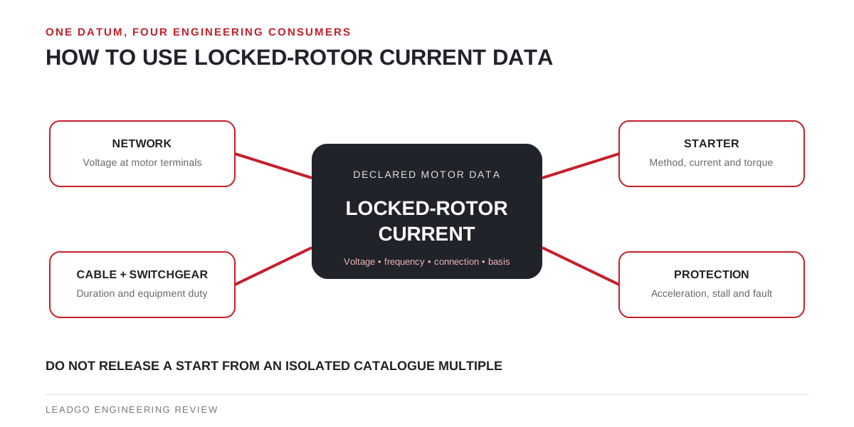
Locked-rotor current is often copied into a data sheet and then left disconnected from the decisions that need it. Its real purpose is to help the motor supplier, power-system engineer and driven-equipment owner analyse the same start.
Confirm what the declared number represents
NEMA MG 1 Part 1 defines locked-rotor current as the steady-state current taken from the line with the rotor locked and rated voltage—and rated frequency for an AC motor—applied. That definition establishes several review questions:
- Is the value RMS line current, apparent power, a ratio, a code or a tested value?
- Which rated voltage, frequency and terminal connection apply?
- Does it describe direct-on-line energisation or current seen through another starting arrangement?
- Is the data for the offered serial design, a guaranteed limit or a typical catalogue value?
- Are tolerances and the applicable standard identified?
Do not mix the defined RMS value with the first instantaneous peak after closing. The latter matters to equipment duty and protection but is not the same datum.
Send one declared value to four separate studies
| Study owner | How locked-rotor current is used | Other evidence needed before release |
|---|---|---|
| Network/transformer reviewer | Calculates starting demand and voltage at the motor terminals | Source impedance, transformer/generator data, feeder impedance, concurrent loads and minimum supply case |
| Starting-method reviewer | Compares direct-on-line, reduced-voltage or drive-assisted cases | Starter topology, transition, bypass, current limit and motor torque available through acceleration |
| Cable and switchgear reviewer | Checks short-duration thermal and equipment-making duties under the specified method | Start duration, starts per hour, ambient/installation factors and device ratings |
| Protection reviewer | Coordinates starting current and time against trip and protection functions | Time-current curves, relay logic, CT data, fault study and allowable stall time |
The table is deliberately not a single formula. Each study consumes the same motor datum but combines it with different controlled inputs.
Keep voltage drop and torque in the same case
A weak supply can reduce voltage at the motor terminals during acceleration. The electrical model must therefore calculate the current and terminal voltage consistently rather than assuming rated voltage at both ends of a long or weak feeder.
Starting torque must be checked at that terminal condition against the load-torque curve. A starting method that limits line current also changes the motor’s available torque. The project should not approve a current target while leaving the acceleration result to a different, incompatible assumption set.
IEC 60034-12:2024 is the current IEC reference for specified starting-performance designs of single-speed three-phase cage induction motors within its stated voltage, duty and starting-method scope. The edition includes provisions on measuring locked-rotor current and torque. Motors outside that scope still require an agreed manufacturer and project basis rather than an improvised extension of the tables.
Request a start-data package, not one cell
For a meaningful study, ask the motor supplier for:
- motor rating, rated current, voltage, frequency and terminal connection;
- declared locked-rotor current basis and tolerance;
- locked-rotor, pull-up and breakdown torque data on a stated basis;
- torque-speed and current-speed information for the offered design when required by the study;
- permissible starting or stall information under the agreed thermal condition;
- rotor and load inertia data in compatible units and referred to a stated shaft;
- restrictions introduced by star-delta, autotransformer, soft starter or variable-frequency drive operation.
The project power-system engineer then adds network and protection inputs. The driven-equipment supplier provides breakaway/load torque and inertia. None of the three parties can close the start alone.
Release criteria for the electrical start
Approve the starting case only when all of the following refer to the same scenario:
- the declared motor data and connection match the purchase specification;
- calculated terminal voltage matches the network case used for motor torque;
- accelerating torque remains positive with the agreed engineering margin through the speed range;
- acceleration time fits the motor thermal and starting limits;
- cable, switchgear and starter duties are acceptable;
- protection permits normal acceleration yet still covers stall and fault conditions;
- the final settings and assumptions are recorded by the responsible reviewers.
If the selected starting method changes, reopen the affected studies. A smaller supply-current number is not a complete motor-start approval.