
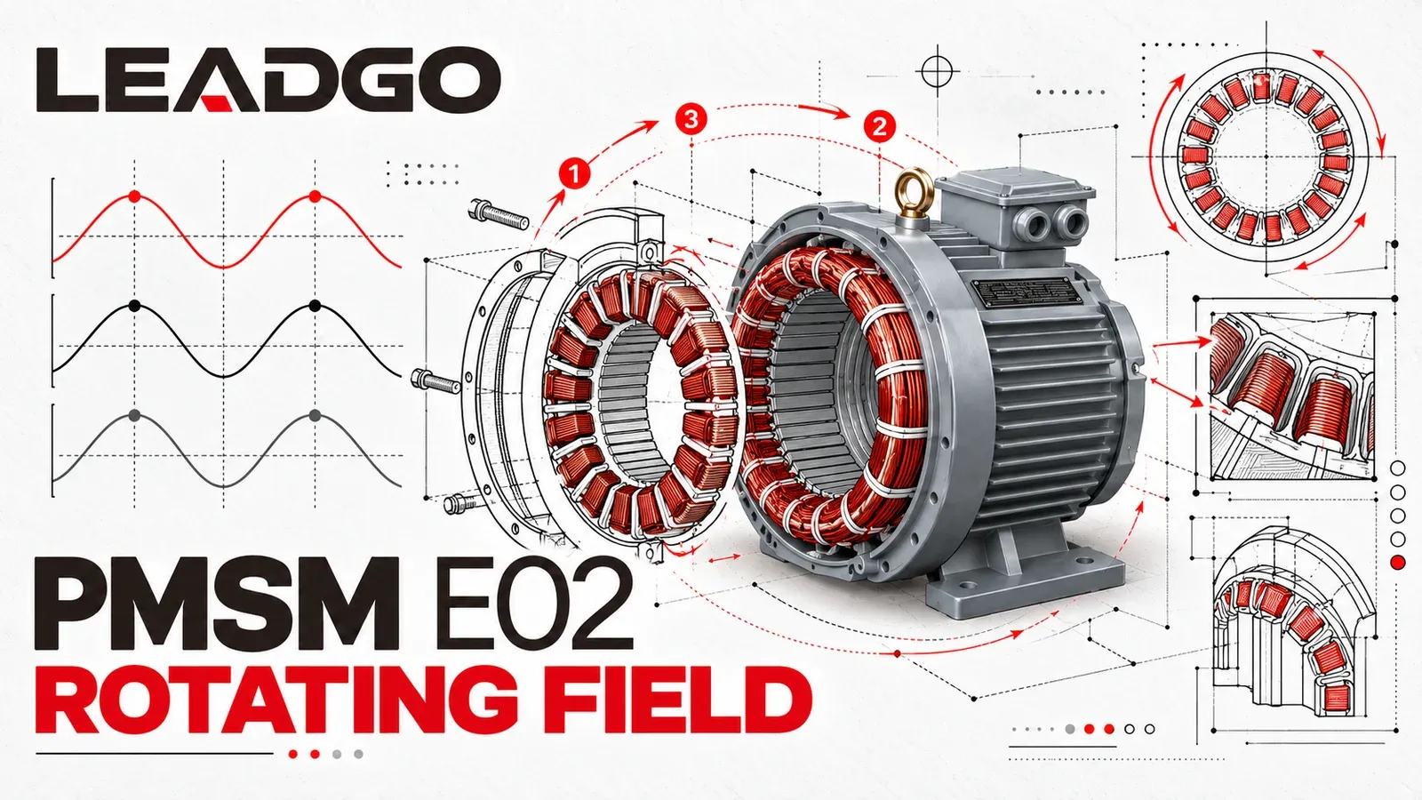
Nothing in a three-phase motor stator physically rotates. The motion comes from stationary windings whose magnetic effects rise, fall and reverse in sequence.
Three balanced phase currents are separated by 120 electrical degrees. Their magnetic fields add together to form one resultant field whose peak travels around the air gap. That rotating field is the common foundation of induction motors, permanent-magnet synchronous motors and wound-field synchronous motors.
From three alternating currents to one moving field
A stator contains coils distributed around a laminated iron core. Current through one phase establishes a magnetic axis. With only one alternating current, the field strength and polarity reverse, but the axis remains fixed.
A balanced three-phase supply changes the result because phases A, B and C reach their positive and negative peaks at different times. At one instant, phase A may provide the strongest contribution. One third of an electrical cycle later, phase B has moved through the corresponding point, followed by phase C.
The magnetic fields do not act independently. Their vector sum forms a resultant field. With a suitable winding layout, the location of that resultant peak moves smoothly around the stator bore while the windings stay in place.
Why 120 electrical degrees matters
In a balanced system, the three currents have equal amplitude and are displaced by one third of an electrical cycle. The stator winding axes are arranged to match that phase relationship. Together they produce a rotating field with a much steadier magnitude than a single-phase pulsating field.
The familiar ideal model is a starting point. Real air-gap flux is also affected by winding distribution, slot geometry, magnetic saturation, harmonics and the drive waveform. Those details change field quality, but not the basic three-phase mechanism.
What sets field speed?
The rotating field travels at synchronous speed:
nₛ = 120f / P
where nₛ is synchronous speed in revolutions per minute, f is electrical frequency in hertz and P is the number of magnetic poles.
For example, a four-pole stator supplied at 50 Hz has a synchronous field speed of:
nₛ = 120 × 50 / 4 = 1,500 rpm
This is the speed of the magnetic field. An induction rotor normally runs below it while producing motoring torque. A correctly controlled PMSM rotor follows it at the same average speed.
What sets the direction?
Phase sequence determines the order in which the resultant magnetic peak moves. Interchanging any two supply phases reverses that sequence and therefore reverses the field direction.
That electrical rule is not a complete reversal procedure. The driven machine may permit only one direction, and a running reversal can impose severe mechanical and electrical stress. A variable-frequency drive may also use a direction command rather than physical rewiring. Confirm the motor, drive, load and site procedure before changing direction.
How different rotors respond
| Rotor type | Interaction with the rotating stator field |
|---|---|
| Cage induction rotor | Relative motion induces rotor current. The resulting rotor field develops torque, so the loaded rotor follows below synchronous speed. |
| Permanent-magnet rotor | Existing magnetic poles align with and follow the controlled stator field during stable synchronous operation. |
| Wound synchronous rotor | A separately excited rotor field locks to the rotating stator field once the machine is synchronized. |
The rotating stator field is therefore common to several AC motor technologies. The main difference is how each rotor establishes its own magnetic field and how the complete machine produces torque.
Why the drive still matters for a PMSM
A variable-frequency drive synthesizes the three phase currents and changes their frequency to control field speed. For a PMSM, the controller also regulates current relative to rotor position. Stable operation depends on the motor-drive system, including position sensing or estimation, current limits, acceleration profile, voltage margin and load dynamics.
The drive does not make the rotating-field principle optional. It gives the controller precise command of the frequency, magnitude and phase of the three stator currents.
A common misconception
Current does not travel from coil A to coil B to coil C as one physical object. Each phase current changes continuously in its own winding. Their magnetic contributions combine to create the moving resultant field.
For the speed relationship that follows from this field, see Synchronous Speed, Rated Speed and Slip. For the rotor-side comparison, see Induction Motor Slip: Why PMSM Rotors Stay in Sync.