
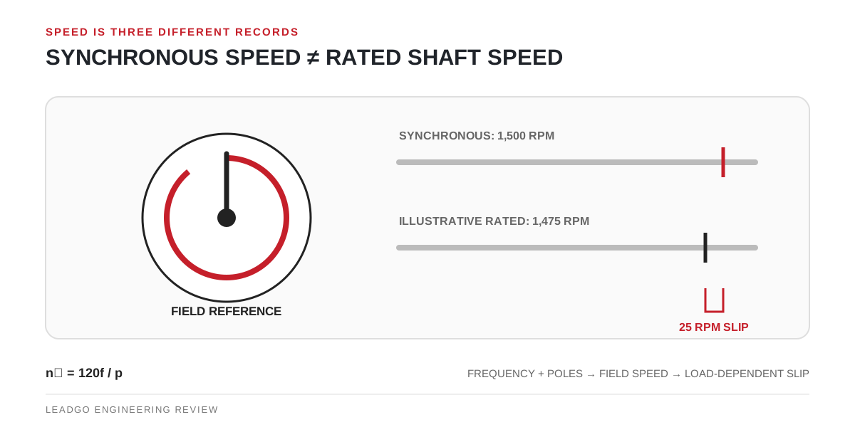
The number printed as motor speed is easy to misuse. Synchronous speed describes the rotating magnetic field. Rated speed describes the shaft at one declared operating condition. The difference between them is slip, which is essential to torque production in an induction motor.
Calculate the field speed first
For a mains-fed AC motor, use the supply frequency and the actual pole count:
Synchronous speed = 120 × frequency / poles
The result is revolutions per minute. It produces the familiar reference speeds below.
| Pole count | At 50 Hz | At 60 Hz |
|---|---|---|
| 2 | 3,000 rpm | 3,600 rpm |
| 4 | 1,500 rpm | 1,800 rpm |
| 6 | 1,000 rpm | 1,200 rpm |
| 8 | 750 rpm | 900 rpm |
| 10 | 600 rpm | 720 rpm |
| 12 | 500 rpm | 600 rpm |
These are magnetic-field speeds, not promises that an induction-motor shaft will run at the same values. The U.S. Department of Energy motor-systems guidebook uses the same equation and explains why induction-motor nameplate speed is lower.
Turn the speed difference into slip
Slip can be expressed in rpm or as a percentage of synchronous speed:
Slip speed = synchronous speed − measured shaft speed
Slip percentage = (synchronous speed − shaft speed) / synchronous speed × 100
Consider an illustrative four-pole motor operating on 50 Hz whose approved nameplate shows 1,475 rpm at rated duty:
- synchronous speed = 120 × 50 / 4 = 1,500 rpm;
- slip speed at that point = 1,500 − 1,475 = 25 rpm;
- slip percentage at that point = 25 / 1,500 × 100 = 1.67%.
The arithmetic does not turn 1.67% into a universal limit. It only describes that named operating point. A site reading taken with the machine unloaded, partially loaded or supplied through a drive belongs to a different condition.
Read the three speeds as different evidence
| Value on the record | What it tells the reviewer | What it does not settle |
|---|---|---|
| Synchronous speed | The field speed created by frequency and pole count | Actual shaft rpm under load |
| Rated/nameplate speed | The declared shaft speed at the maker’s stated rating | Speed at every process load or voltage |
| Measured operating speed | What the shaft did during a documented site condition | Whether the motor is correctly selected without load data |
Before comparing values, verify that frequency, pole count, control mode and load condition belong to the same machine. A drive display frequency is useful evidence, but a calibrated shaft-speed reading and the drive’s actual output conditions provide a stronger diagnostic record.
Where replacement reviews go wrong
One common error is to replace a 50 Hz motor with a 60 Hz selection using only the kW and frame. Frequency changes synchronous speed, so the driven equipment may see a different flow, pressure, surface speed or lubrication condition. Another error is to interpret a lower site rpm as an electrical fault before confirming whether the motor is carrying more torque than the comparison case.
For belt drives and gearboxes, record the ratio as well as motor rpm. For directly coupled pumps and fans, obtain the driven-equipment curve and allowable speed range. The DOE guidebook notes that centrifugal applications are speed-sensitive; that makes a small rpm difference an engineering input, not a cosmetic nameplate discrepancy.
Release the speed decision only with matching records
Use this compact close-out set:
- motor manufacturer, model, serial number and controlled nameplate record;
- confirmed pole count rather than an assumed model-code suffix;
- supply or drive output frequency at the reviewed operating point;
- rated speed and its stated duty;
- measured shaft speed, load condition and instrument details;
- driven-equipment speed range, transmission ratio and process consequence.
If those records do not agree, do not average the values. Identify which condition changed and request the missing motor or load evidence. The current general IEC reference is IEC 60034-1:2026, but the applicable project specification and the exact manufacturer’s data remain the controlling basis for acceptance.