
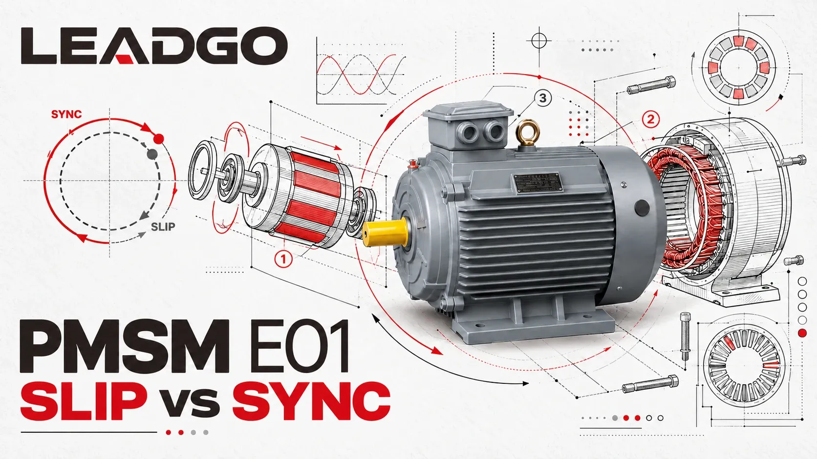
An induction motor and a permanent-magnet synchronous motor can use similar three-phase stators. Their rotors respond to the rotating magnetic field in different ways, and that difference starts with slip.
The induction rotor needs a small speed difference to create its own current. A PMSM rotor already carries a magnetic field, so a compatible drive can keep it locked to the stator field in normal operation.
Slip is a speed relationship
The stator currents create a magnetic field that rotates at synchronous speed. For a machine with supply frequency f and P magnetic poles:
nₛ = 120f / P
where nₛ is synchronous speed in revolutions per minute.
An induction motor’s cage rotor turns at nᵣ, slightly below nₛ while it is producing motoring torque. Per-unit slip is:
s = (nₛ − nᵣ) / nₛ
Slip is often reported as a percentage by multiplying the result by 100.
Why the induction rotor must fall behind
The cage rotor contains conducting bars joined by end rings. The moving stator field cuts those conductors and induces rotor voltage and current. The rotor current establishes a magnetic field that interacts with the stator field to produce torque.
If the rotor reached the same speed as the rotating field, their relative motion would disappear. Induced rotor voltage and current would fall toward zero, and the motor could not maintain normal induction torque under load. The loaded operating point therefore sits below synchronous speed.
As mechanical load rises, the rotor generally slows slightly relative to the field. The resulting increase in slip raises induced rotor current and allows the motor to develop more torque. The exact slip is not a fixed percentage for every motor or every load.
A worked example
A four-pole motor on a 50 Hz supply has a synchronous speed of:
nₛ = 120 × 50 / 4 = 1,500 rpm
If its measured shaft speed is 1,455 rpm at the operating point:
s = (1,500 − 1,455) / 1,500 = 0.03 = 3%
This calculation describes the speed difference. It does not by itself diagnose efficiency or load. The US Department of Energy cautions that slip-based load estimates carry uncertainty because nameplate full-load speed is rounded and actual speed also responds to voltage and operating condition.
Why a PMSM stays in step
A permanent-magnet synchronous motor has magnetic poles on or inside the rotor. The rotor field does not depend on continuous cage-current induction. A compatible drive supplies controlled stator current so that the rotating stator field and the rotor magnetic field turn at the same average speed.
Torque is associated with the angular relationship between those magnetic fields, not with a continuous difference in their rotational speeds. Load changes affect current demand and torque angle while the controller maintains synchronism within the approved operating envelope.
This description applies to stable controlled operation. Starting method, rotor-position sensing or estimation, current limits and pull-out or loss-of-synchronism protection still matter.
Induction motor and PMSM compared
| Question | Cage induction motor | Drive-fed PMSM |
|---|---|---|
| How is the rotor field established? | Current induced in rotor conductors | Permanent magnets provide rotor excitation |
| Normal loaded shaft speed | Below synchronous speed | At synchronous speed |
| Is steady speed slip required for torque? | Yes | No |
| What changes as load rises? | Slip and rotor current generally rise | Controlled stator current and torque angle change |
| Important additional equipment | Starter or drive, depending on duty | Compatible PMSM drive and commissioning |
What “no slip” does not mean
No slip does not mean no loss. A PMSM still has stator winding loss, core loss, bearing and windage loss, inverter loss and design-dependent rotor or magnet eddy-current loss. A technology comparison needs matched torque, speed, duty cycle, cooling and drive conditions.
An induction motor may remain the practical choice where supply simplicity, installed service capability, capital cost or a particular constant-load duty carries more weight. A PMSM can be compelling where the complete operating profile benefits from synchronous control and the motor-drive system is properly matched.
What to confirm before choosing
- Define continuous and peak torque across the required speed range.
- Record duty cycle, starts per hour and overload duration.
- Confirm fixed-frequency, line-start or drive-fed operation.
- Compare motor-and-drive efficiency at the actual operating points.
- Check cooling, enclosure, ambient condition and installation constraints.
- Confirm commissioning and service responsibility for the complete drive system.
For the broader buying questions, see Permanent-Magnet Motor Questions Buyers Ask Before Ordering. For a topology that starts from the line before pulling into synchronism, see Line-Start Permanent-Magnet Motors Without a Drive.