
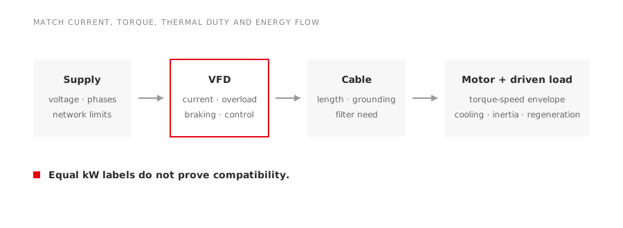
Two devices can carry the same kW label and still be a poor match. The drive supplies current and switching voltage; the motor produces torque; the machine sets the speed-torque demand. All three must agree.
Direct answer
Match a VFD to a motor through seven checks:
- supply and motor connection;
- continuous output current;
- overload current and duration;
- required torque over speed;
- motor cooling and thermal feedback;
- insulation, cable and bearing effects;
- acceleration, deceleration and regenerative energy.
Motor kW is a useful catalogue filter, not the final selection rule.
Start with nameplate current
Use the motor rated current for the actual voltage, frequency and winding connection. Confirm that the drive’s continuous output-current rating meets the requirement after applicable derating.
Derating may be required for high ambient, altitude, high switching frequency, enclosure installation, poor cabinet ventilation or an unusual output frequency. The manufacturer’s drive manual controls those factors; a universal multiplier is not reliable.
If several motors share one VFD, selection and protection change substantially. Add current and evaluate individual overload protection, contactor switching restrictions, cable layout and whether all motors always operate together.
Classify the load torque
The load curve determines current demand and thermal behaviour.
| Load type | Typical behaviour | What to verify |
|---|---|---|
| Centrifugal fan/pump | Torque generally falls strongly with speed | System curve, minimum flow/head, resonance |
| Conveyor | Often near constant torque | Breakaway torque and loaded starting |
| Positive-displacement pump | Often constant torque | Pressure limit and low-speed lubrication |
| Winder/hoist | May regenerate or require constant power | Braking, overspeed and safety functions |
| Mixer/extruder | Process-dependent, high breakaway possible | Material condition and overload cycle |
Obtain the actual torque-speed curve where possible. The labels “heavy duty” and “normal duty” are manufacturer rating categories, not substitutes for the load profile.
Check overload as current over time
A brief high-torque event and a repeated overload every minute do not impose the same heating. State magnitude, duration, interval and the motor speed at which it occurs.
Acceleration requires torque beyond the load torque to overcome inertia. If the selected current limit is too low, acceleration lengthens and both motor and drive may heat more than expected. If the process can jam, define how stall is detected and cleared.
Low speed can be the hardest thermal point
A shaft-mounted fan slows with the motor. A constant-torque machine may still demand substantial current while ventilation has fallen sharply. Options include motor derating, an independently powered fan, a different speed range or a motor designed for the duty.
Specify minimum continuous speed, time spent there, ambient and required torque. Confirm thermal-sensor type and how the drive uses it. A current model alone cannot detect every cooling problem.
Cable and switching affect the motor terminals
The VFD output is a switched waveform. Cable length, cable construction, grounding, switching speed and motor impedance influence terminal-voltage stress and electromagnetic interference.
Request the drive manufacturer’s permitted motor-cable length and any required output reactor or filter. Verify the motor’s converter-duty basis. For long cables or older motors, a system review is especially important.
Common-mode voltage can also drive bearing currents. Bearing insulation, grounding brushes, cable symmetry and common-mode filtering are application tools, not automatic requirements for every installation. The guide to VFD common-mode and differential-mode interference explains the distinction.
Acceleration and stopping need an energy path
Set acceleration from available torque and process limits. Set deceleration from load inertia and the path for returned energy.
During a rapid stop, a high-inertia or overhauling load can raise the DC-bus voltage. Depending on duty, the design may use a longer coast/deceleration time, a braking unit and resistor, a regenerative front end or another approved method.
Define:
- total reflected inertia;
- maximum and normal stopping time;
- stops per hour;
- whether the load can drive the motor;
- emergency-stop philosophy;
- resistor location, temperature and protection where used.
Do not overlook speed limits
Above base frequency, available motor torque normally changes because voltage cannot continue rising in proportion to frequency. The load may enter a constant-power region, and the rotor, bearings and driven equipment must tolerate the speed.
Below base speed, torque may be available but cooling can be limiting. Write the continuous and short-time torque envelope into the specification instead of giving only minimum and maximum frequency.
Commission as a system
Record motor data accurately in the drive. Verify rotation, current, acceleration, thermal feedback, minimum-speed cooling, maximum-speed vibration and stopping behaviour. Tune control parameters within the equipment manufacturer’s method; do not copy settings from a different motor simply because the kW matches.
LEADGO lists YVP variable-frequency motors and the LD800 general-purpose drive separately because final compatibility depends on the selected rating and application.