
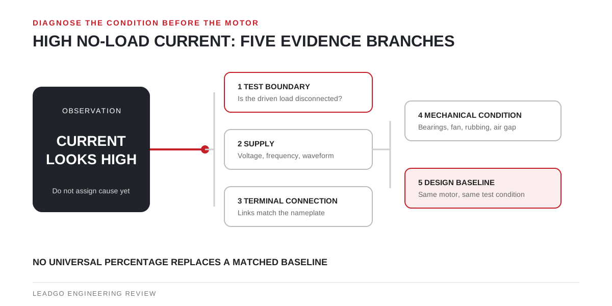
“The motor has high no-load current” is a diagnosis only after no load and high have been defined. A reading taken with a belt attached, the wrong terminal links or an unmatched voltage/frequency condition cannot be compared fairly with a factory value.
Establish a repeatable no-load test
NEMA MG 1 Part 1 defines no-load current as the line-terminal current when rated voltage is applied at rated frequency with no connected load. For a field investigation, add the practical details needed to reproduce that boundary:
- confirm motor identity and approved winding connection;
- isolate the driven machine where the work method permits it;
- record line-to-line voltages, frequency and all three line currents;
- note whether power comes from mains, a test source or a variable-frequency drive;
- allow the current to stabilise under the governing procedure;
- record bearing, fan and rubbing observations rather than calling every unloaded run friction-free.
The test must follow the motor and test-equipment manufacturers’ safety instructions. An uncoupled run introduces rotating-equipment risks and is not a casual diagnostic step.
Sort the evidence before opening the motor
| Diagnostic branch | Evidence to collect | Finding that changes the next step |
|---|---|---|
| Test boundary | Coupling state, auxiliaries, fan configuration, run duration | A connected gearbox, pump or belt means the test is not the intended no-load comparison |
| Supply quality | Three line voltages, frequency, waveform/control source | Wrong voltage-frequency relationship or material phase inequality must be resolved before motor conclusions |
| Terminal connection | Nameplate diagram, link positions, cable identification | Links do not match the rated supply and winding connection |
| Mechanical condition | Free rotation, bearing sound/temperature, fan contact, air-gap or rub evidence | Current changes with a confirmed mechanical correction |
| Winding/design history | Factory result, prior test, winding data, repair record | A post-repair shift exists under the same controlled condition |
| Instrumentation | Meter identity, range, calibration status and simultaneous/sequence method | Apparent phase difference follows the instrument or measurement method |
This order avoids a costly mistake: dismantling the motor before proving that the external condition is correct.
Why one percentage cannot decide acceptance
No-load current contains a substantial magnetising component. It is influenced by magnetic design, frame and pole configuration, air gap, winding details and the applied supply. Two motors with the same output rating can therefore have different legitimate readings.
EASA’s high-current guidance treats original and rewound motors as different investigative cases. That distinction is useful in procurement and repair work: a pre-repair test, winding record and final test under a matched condition tell a stronger story than a generic table taken from another design.
For low-voltage cage induction motors within its stated scope, IEC 60034-28:2012 provides procedures for obtaining equivalent-circuit quantities. It does not turn an uncontrolled site reading into a motor-specific acceptance value. The agreed inspection and test plan still needs to say which method and comparison apply.
Use the pattern across phases and time
A total magnitude and a phase pattern answer different questions. If all three currents move together after a controlled supply change, investigate the common electrical or magnetic condition. If one phase separates materially from the others, verify supply inequality, connection, winding resistance and instrumentation using the applicable procedures.
Also note when the observation occurs. A cold start, a stabilised run and a reading after repair are not interchangeable snapshots. Trend data should preserve the same boundary so that a change is attributable rather than merely visible.
Decide whether the evidence points outside or inside
Keep the motor out of internal repair escalation when the current returns to its approved baseline after correcting supply, terminal links, driven load or measurement setup. Escalate to the manufacturer or qualified service facility when the controlled reading remains abnormal and the external checks are closed.
The escalation package should include:
- nameplate, serial number and connection diagram;
- three voltages and currents with frequency and source;
- coupled/uncoupled condition and mechanical observations;
- factory or historical result for the same machine;
- repair and winding history where applicable;
- instruments, dates, temperatures and responsible reviewer.
This package lets the recipient evaluate design data, winding condition, air gap, rotor and core evidence without guessing which test was actually performed.