
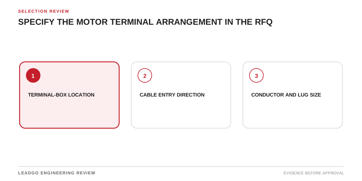
A motor may satisfy its electrical rating and still arrive with a terminal arrangement that cannot accept the site cables. A box on the wrong side, an entry face blocked by the baseplate, insufficient room for the specified lugs or an inaccessible earthing point can force field modifications at the worst possible stage. These are interface failures, not minor drafting issues.
The RFQ should treat the motor terminal system as the meeting point of two designs: the manufacturer’s insulation and enclosure design, and the project’s cable, support and installation design. Both sides need controlled inputs before the general arrangement and terminal drawings are frozen.
Applicability and engineering boundary
This method applies to industrial motors with project-designed power and auxiliary cabling, including direct-on-line, starter-fed and VFD-fed duties. It is particularly useful when cables are large, multiple conductors per phase are proposed, the motor is installed in a restricted space or hazardous-area requirements apply.
It does not prescribe universal clearances, gland types or terminal dimensions. Those depend on voltage, cable construction, termination system, enclosure, certification, installation rules and the manufacturer’s validated design. The responsible electrical engineer must establish project requirements; the motor supplier must confirm what its offered construction can accommodate.
Engineering tool: terminal-interface freeze matrix
Complete the matrix before drawing approval. For every row, record the buyer input, supplier response, drawing reference, open action and approval owner.
| Interface item | Buyer must define | Supplier must confirm | Freeze evidence |
|---|---|---|---|
| Viewing convention | Drive-end or non-drive-end reference | Drawing uses the same convention | Marked orientation sketch |
| Main box position | Required side and installation orientation | Offered position and any constraints | Certified GA |
| Entry face and direction | Bottom, side or other permitted approach | Machinable faces and approved entry zones | Terminal-box detail |
| Cable route | Tray, trench, conduit and final approach | Entry remains accessible and supported | Coordinated layout |
| Number of cables per phase | Cable schedule and parallel runs | Terminal system accepts the quantity | Connection schedule |
| Conductor size and construction | Material, cross-section and class | Bending and termination envelope is adequate | Cable-to-terminal check |
| Lug type and palm geometry | Proposed lug standard and dimensions | Stud, palm, spacing and hardware match | Lug drawing and terminal detail |
| Phase arrangement | Required phase order and identification | Terminal sequence and links are shown | Connection diagram |
| Internal clearances | Project voltage and termination concept | Validated insulation arrangement is maintained | Supplier design confirmation |
| Cable bending space | Cable outside diameter and bend requirement | Box depth and access permit installation | Scaled routing review |
| Glands or entry plate | Gland material, thread/hole system and sealing duty | Plate thickness, area and earthing suit entries | Approved entry-plate drawing |
| Main earthing | Conductor size and connection philosophy | External/internal earth points and hardware | Earthing detail |
| Neutral or star point | Whether access is required | Separate enclosure or internal arrangement | Schematic and GA |
| Space-heater terminals | Supply and isolation philosophy | Voltage, marking and terminal allocation | Auxiliary schematic |
| Sensor and accessory circuits | RTD, PTC, encoder, brake or fan circuits | Segregation, terminals and entries are adequate | Terminal schedule |
| Environmental sealing | IP, corrosion, drainage and condensation requirements | Gaskets, plugs and orientation preserve enclosure | Construction declaration |
| Installation access | Tool, cover-removal and inspection envelope | Covers and terminals can be reached safely | 3D/layout access review |
The last column prevents verbal agreements from disappearing. A redlined sketch can start coordination, but the closed decision belongs on the approved supplier drawing and project cable documentation.
Decision steps before drawing release
- Fix the reference orientation. State how left and right are viewed. Many terminal-position disputes begin with different viewing conventions.
- Overlay the motor and site layout. Include foundation, driven equipment, guards, pipes, walkways and cable supports.
- Build the actual cable envelope. Use the proposed cable count, outside diameter, lug geometry, bend constraints and support method—not only conductor area.
- Review power and auxiliary circuits separately. Confirm segregation, entries, terminal markings and isolation requirements.
- Check installation sequence. Determine whether cables can be pulled, glanded, bent and torqued after the motor and coupling are in place.
- Resolve hazardous-area or environmental constraints. Verify approved entries, sealing and certificate limitations where applicable.
- Freeze both documents together. Close the supplier terminal drawing and project cable/interface drawing at compatible revisions.
Supplier data and RFQ requirements
Provide the supplier with the site orientation, cable route, supply system, cable schedule, cable construction, proposed lug dimensions, number of parallel conductors, earthing arrangement and auxiliary I/O list. Include installation restrictions such as trench position, minimum access side or prohibited entry faces.
Require the bid to identify the offered main and auxiliary box positions, usable entry faces, box material, entry-plate arrangement, terminal sizes, stud or palm details, permitted cable count, earthing points and enclosure protection. Ask for preliminary dimensional drawings early enough to compare bids.
After award, request a scaled terminal-box drawing, internal terminal layout, connection diagram, terminal schedule and certified GA. The drawing should show cover-removal envelope, entry zones, terminal identification, links, earth points, drainage or breather features if supplied, and applicable hazardous-area marking or limitations. Any field drilling or box rotation must be explicitly permitted by controlled instructions rather than assumed.
Common errors that surface during installation
- Writing “terminal box on right” without a viewing direction. Buyer and supplier may both comply with different interpretations.
- Checking conductor area but not the lug. The cable fits electrically while the palm, stud hole or barrel conflicts mechanically.
- Ignoring parallel cables. One terminal may not accept two lugs, and stacking can alter clearances or hardware loading.
- Assuming any blank face can be drilled. Structural, sealing, clearance or certification restrictions may prohibit it.
- Leaving auxiliary circuits until late. Sensor, heater, encoder or brake entries then compete for space.
- Forgetting cable support loads. The terminal box and glands should not become the cable support system unless designed for that duty.
- Approving a GA without internal details. External dimensions alone cannot prove bend space and terminal access.
- Treating site rotation as harmless. Drainage, cover access, gasket seating, internal leads and marking may be affected.
Coordinating cable entry and maintenance access
A scaled review is more useful than a statement of compliance. Model or sketch the cable from its final support to the terminal palm. Include the gland body, locknut or sealing components, conductor breakout, lug barrel and the tool path required for bolting. Check that the cover can be removed without disturbing permanent pipework or guards.
Maintenance also needs a safe way to isolate, inspect, test and retorque connections. If the terminal box faces a wall or sits directly above a trench edge, a dimension that is technically possible may still be impractical. Record the required access envelope on the layout so later package changes do not consume it.
For multiple motors, avoid assuming one arrangement suits every location. The same motor design may require alternative box positions or cable routes. Identify variants by asset tag and control them in the document register.
Acceptance and closure conditions
The interface is ready for manufacture when the approved drawings agree on orientation, box position, entry face, cable count, lug/terminal geometry, earthing and auxiliary circuits. All deviations are recorded, and no open item is deferred to site without an approved method and assigned owner.
At factory inspection or document review, compare the actual terminal construction with the approved drawings. Verify markings, terminals, links, earth points, entry plate, accessories and supplied loose hardware. Where certificate-controlled construction applies, confirm the delivered configuration and instructions match the accepted documentation.
At site, inspect for transport damage, correct entries, cable support, sealing, phase identification, connection torque according to the approved instructions, and segregation of auxiliaries. Close the record with the as-built connection diagram and photographs where project practice requires them. Energisation should not be used as the first proof that the cable and motor designs fit together.