
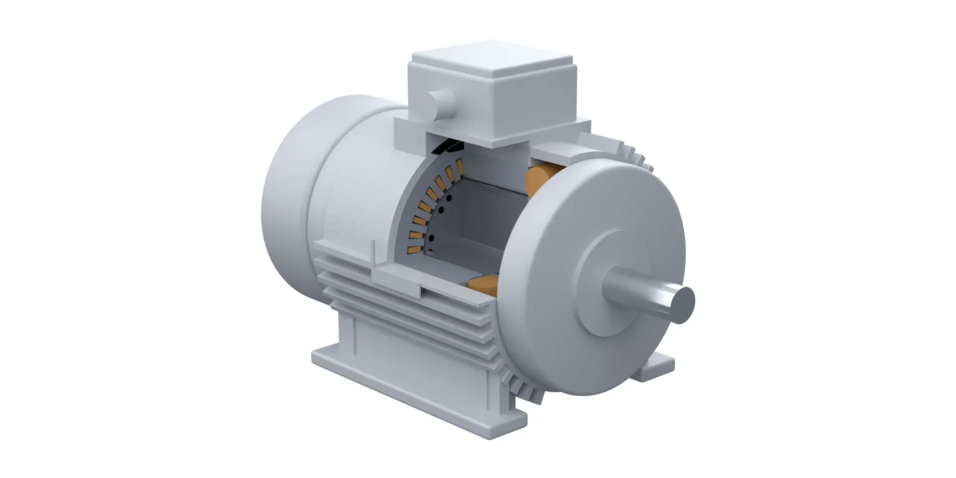
An induction motor is an AC motor in which the current in the rotor is not supplied from outside. It is induced there by the rotating magnetic field of the stator. Nothing is wired to a cage rotor, so it has no brushes and no electrical connection to wear out. The rotor always runs slightly slower than the field, and that gap in speed, called slip, is what makes torque. The same machine is called an asynchronous motor, and the three-phase squirrel-cage version is the one this page describes.
This page explains how an induction motor works, what is inside it, the main types, how torque changes with speed, how it starts, and where it fits. Each section links to a deeper article. The machine described here is the three-phase squirrel-cage motor. The figures are schematics, not drawings of a specific motor design.
The short answer
Four facts cover most of what you need.
- The stator makes a rotating field. A three-phase winding in a laminated steel core, fed from a three-phase supply, produces a magnetic field that turns around the bore at a speed set by the supply frequency and the number of poles.
- The rotor carries conductors, usually a cage. The conductors sit in a laminated steel core. The most common arrangement is a cage of bars joined by end rings. Davis calls the squirrel-cage rotor the most common type of AC rotor.
- The current in the rotor is induced. The turning field sweeps across the rotor conductors and induces a voltage in them. The resulting current feels a force from the same field, and that force is torque.
- The rotor runs a little slower than the field. If it caught up, there would be nothing sweeping across the conductors and no torque.
The word induction comes from the second step. Hughes and Drury point out that a wound-rotor induction motor is physically similar to a three-phase transformer: the stator winding plays the primary and the rotor winding plays the secondary. The stator feeds the rotor by induction, the way a transformer primary feeds its secondary.
How an induction motor works
Three-phase current in the stator winding produces a field that sweeps around the bore. Because the bars turn more slowly than the field, the field passes across them. A voltage is induced in each bar, current flows through the bars and end rings, and the field pushes on that current. The push acts tangentially on the bars, and that push is torque.
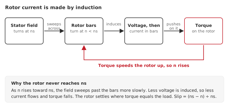
Figure 1. The rotor current is made by the sweep of the field across the bars. The loop explains why the rotor never reaches field speed.
Hughes and Drury put it plainly: the rotor is dragged along by the rotating field, but it can never run quite as fast as the field. The reason is in the loop of Figure 1. As the rotor speeds up, the field sweeps past the bars more slowly, so less voltage is induced, less current flows and torque falls. The rotor settles at the speed where its torque matches the load.
Field speed and slip
The speed of the field is set by frequency and poles. In rpm it is 120 times the frequency divided by the number of poles. At 50 Hz that gives:
| Poles | Field speed at 50 Hz |
|---|---|
| 2 | 3,000 rpm |
| 4 | 1,500 rpm |
| 6 | 1,000 rpm |
| 8 | 750 rpm |
The rated speed on a nameplate is always a little below these figures. The gap, as a fraction of the field speed, is the slip:
Slip = (field speed − rotor speed) ÷ field speed
Hughes and Drury work through a motor whose field turns at 1,800 rev/min and whose full-load speed is 1,728 rev/min. The slip speed is 72 rev/min and the slip is 72 ÷ 1,800 = 0.04. For the field-speed formula, a worked slip calculation and the evidence needed before changing frequency, see synchronous speed, slip and rated motor speed.
What is inside
An induction motor has a short list of parts: a frame, a stator core with its winding, a rotor on a shaft, two bearings in end shields, a cooling fan with its cover, and a terminal box. The stator and rotor cores are stacks of thin steel laminations.
The rotor is the part that varies. Hughes and Drury describe two types.
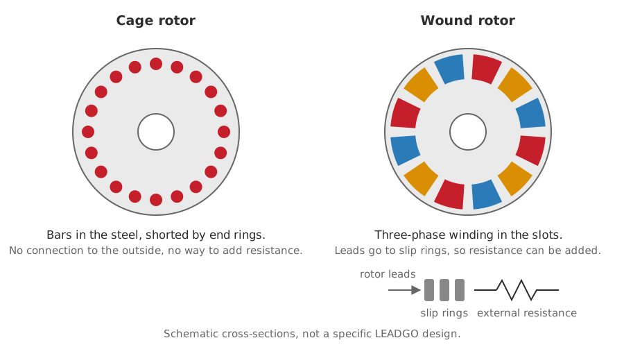
Figure 2. A cage rotor is a closed circuit. A wound rotor brings its windings out to slip rings.
Cage rotor. A stack of laminations carries copper or die-cast aluminium bars joined by end rings. There is no means of making a direct electrical connection to the rotor, which underlines that the rotor currents are induced by the air-gap field. Because the cage is permanently short-circuited, nothing outside can change the resistance of the rotor circuit once the rotor is built. Hughes and Drury call that a significant drawback, and it is the reason the second type exists.
Wound rotor. The slots hold a three-phase winding much like the stator’s, connected in star, with the three ends brought out to slip rings. Brushes on the rings make the rotor circuit available from outside, so resistance can be added in each phase. That is useful for some starting and speed-control duties, at the price of rings and brushes to maintain.
Types of induction motor
By rotor
Squirrel-cage and wound-rotor, as above. Squirrel-cage is the more common of the two. CEMA’s conveyor handbook lists wound-rotor motors with stepped secondary control as one of the drive arrangements, which shows where the second type still earns its place.
By supply
Three-phase induction motors are what this page describes. Single-phase induction motors also exist for supplies without three phases. NEMA MG 1 notes that single-phase AC motors are usually induction or series-wound types.
By NEMA design letter
For low-voltage squirrel-cage motors NEMA sorts torque behaviour into design letters. CEMA’s handbook summarises them as follows.
| Design | Locked-rotor torque | Pull-up torque | Breakdown torque | Starting current | Running slip |
|---|---|---|---|---|---|
| A | Low to moderate | Low | High | High | Small |
| B | Moderate | Moderate | Medium to high | Moderate | Moderate |
| C | Moderate to high | High | Medium | Medium to low | Medium |
| D | High | High | Moderate to low | Low | 5% or more at rated load |
Based on CEMA, Belt Conveyors for Bulk Materials, and NEMA MG 1-2024 section 1.19.1.
Design B has moderate values across the table, which is why it suits general-purpose duty. Design D accepts a higher running slip in return for high starting torque, which suits loads with heavy peaks such as oil well pumping units. See why NEMA Design D is specified for oil well pump motors. The letters belong to the NEMA system.
Torque against speed
An induction motor’s torque is not constant as it accelerates. Figure 3 shows the shape.
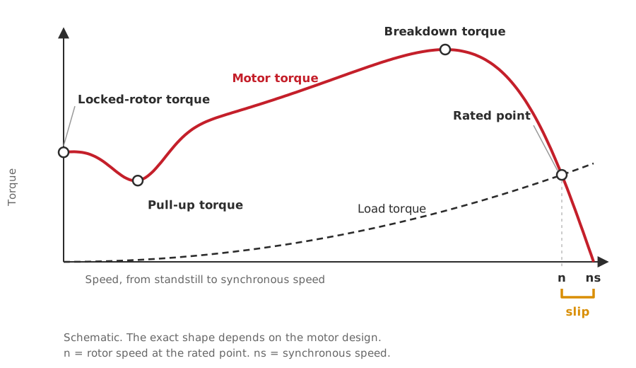
Figure 3. The motor accelerates while its torque exceeds the load torque, and settles where the two curves cross.
NEMA MG 1 defines the labelled points.
- Locked-rotor torque is the minimum torque the motor develops at rest, with rated voltage at rated frequency.
- Pull-up torque is the lowest torque the motor develops while accelerating from rest.
- Breakdown torque is the maximum torque the motor develops at rated voltage and frequency without an abrupt drop in speed. Hughes and Drury call the same quantity pull-out torque.
- Rated torque is the torque needed to produce rated power at full-load speed.
The motor accelerates as long as its torque is above the load’s. It settles where the curves cross, close to synchronous speed and on the steep part of the curve. If the load rises, the rotor slows slightly, slip grows, more current is induced and more torque is produced until the two match again. The rated point sits below the breakdown peak, and that gap is the margin for load peaks. Because torque varies with the square of the voltage, a supply sag eats into it.
For project application, use the practical torque-speed curve guide and connect its electrical start case to the locked-rotor current data review.
How an induction motor starts
At standstill the field already sweeps past the whole cage, so an induction motor produces torque from rest. That is the difference from a synchronous motor, which Gieras and Shen state is not self-starting. The question is how hard to start it.
| Method | What it does | What to watch |
|---|---|---|
| Full-voltage start | Connects the motor straight to the supply | NEMA Design A to D motors are built to withstand it. The supply sees a large starting current, and a deep voltage dip can drop out contactors |
| Reduced-voltage start | Starts at lower voltage through an autotransformer, a star-delta arrangement or an electronic soft starter | Torque varies with the square of the voltage, so a reduced start also gives less starting torque |
| Variable-frequency drive | Raises voltage and frequency together from a low value | Needs a drive matched to the motor, and cooling at low speed |
The SPE Petroleum Engineering Handbook notes that reduced-voltage methods, autotransformer starters, electronic soft starters and variable frequency drives, can cut the generator capacity a plant needs, because they limit the voltage dip. The relation between torque and voltage comes from Gieras and Shen’s comparison of synchronous and induction motors, which lists the induction motor’s torque as proportional to the square of the input voltage.
The motor’s locked-rotor current is set by its design, so the supply’s limit and the starting method are chosen together. Related article: motor code letters and starting current. For a side-by-side of direct-on-line, star-delta, soft starter and drive starts, see which start method. A starting voltage dip also has to be checked against the load, which the starting voltage-drop review covers. For high-voltage motors, see starting methods for high-voltage motors.
Efficiency and power factor
An induction motor loses energy in four places: the stator winding, the rotor winding, the steel core and friction with windage. Hughes and Drury’s treatment of the equivalent circuit separates them. The rotor winding loss is the one a magnet rotor does not have, and it grows with slip, so other things equal a lower slip means a lower rotor loss.
Efficiency is classified under IEC 60034-30-1 as IE1 to IE5. In China the equivalent scale is GB 18613—2020, whose grades 3, 2 and 1 correspond to IE3, IE4 and IE5. LEADGO’s YE3, YE4 and YE5 series are the IE3, IE4 and IE5 versions of the same platform. For a Chinese grade, see GB 18613 and IE classes. To compare classes over the life of a project, see IE3 vs IE4 vs IE5.
Power factor of an induction motor is lower at light load, because the magnetising current stays almost the same while the active current falls. Why motor power factor falls at light load shows how to check the reading with measured kW and kVA before choosing a remedy. Nameplate efficiency is a rated-point figure, so motor efficiency at partial load is the one to read for an energy decision. For the drive system rather than the motor alone, see IE for the motor, IES for the system.
Running an induction motor on a drive
A variable-frequency drive gives an induction motor adjustable speed. Hughes and Drury point to published guidance for it: NEMA MG 1 (part 31 in the edition they cite) on squirrel-cage motors with adjustable-voltage and adjustable-frequency controls, and IEC 60034-17 and IEC 60034-25 on converter-fed induction motors. They also note that very-low-speed operation can call for a separate cooling fan, because the shaft-mounted fan moves little air when it turns slowly.
The checks that matter are the drive rating against the motor, cooling at low speed, insulation stress from the drive’s switching, and bearing currents. VFD cable length and motor insulation stress, VFD carrier frequency and VFD bearing currents take the last two in turn. See matching a VFD to a motor, running a motor at low speed without cooling failure and flameproof motors on a VFD. For duty that is variable-speed all the time, keeping the induction motor or moving to a PM motor sets out the choice.
Where induction motors are used
An induction motor suits constant-speed duty running near rated load. Typical uses are fans, pumps, compressors, conveyors and mixers, machine tools, packaging and printing machinery, and agricultural machinery. Mining, oil and gas, cement and chemical plants use induction motors too, with the enclosure and certification the area demands. The industry pages describe the duty in each: oil and gas, mining, cement, metallurgy, chemical and rubber and plastics.
Induction, synchronous and DC motors compared
| Induction motor | PM synchronous motor | Brush DC motor | |
|---|---|---|---|
| Rotor current | Induced | None, the field comes from magnets | Supplied through brushes and a commutator |
| Speed under load | Falls slightly with load (slip) | Constant, set by frequency | Set by supply voltage and load |
| Starting | Self-starting | Needs a drive or a starting cage | Self-starting |
| Speed control | Variable-frequency drive | Variable-frequency drive | Simple voltage control |
| Maintenance | No brushes on a cage rotor | No brushes | Commutator and brushes |
For the synchronous column, what a permanent magnet synchronous motor is goes through the comparison in detail, and permanent magnet against induction motors in oilfield duty applies it to a real application. On brushes, Gieras and Shen note that about 90% of the maintenance of permanent magnet brush DC motors relates to the commutator and brushes, and that their speed is easy to control. A cage rotor has no brushes to maintain.
Common faults at a glance
Most induction motor problems show up first as a change in current, temperature, noise or vibration. These articles take the common ones in turn.
- Current that is too high at no load. Use the high no-load current diagnostic path to separate the test boundary, supply, connection and machine evidence.
- Supply problems. Voltage unbalance.
- Insulation and winding tests. Insulation resistance and polarization index, high-potential testing limits and surge comparison testing.
- Heat. Derating for altitude and ambient temperature and F-class insulation, B-class rise.
- Vibration and bearings. What motor vibration analysis can and cannot detect.
- Repair or replace. Motor rewind versus replace.
How to choose an induction motor
- Power and speed. Rated power, and speed through the pole number. A 4-pole motor at 50 Hz has a field speed of 1,500 rpm and a full-load speed a little below it.
- Supply. Voltage and frequency, and whether the motor will run from a drive.
- Duty. Continuous or intermittent, and the load profile. Motor duty types S1 to S10 explains what each one commits you to.
- Starting. The load’s breakaway torque and inertia, and the supply’s limit on starting current.
- Efficiency class. IE3, IE4 or IE5, chosen on running hours and tariff, not on rating.
- Mounting and frame. IEC or NEMA frame, and the mounting arrangement. The NEMA and IEC frame chart and frame size against power rating help here.
- Environment. Ambient temperature, altitude, humidity, dust, and any hazardous-area requirement, which changes the enclosure.
- Protection and monitoring. Thermal protection, heaters and sensors the site expects.
LEADGO’s three-phase induction range is on the induction motors page. The general-purpose series are YE3 at IE3, YE4 at IE4 and YE5 at IE5, and YVP for variable-frequency duty. The motor selector narrows the choice from your application. If you already have the duty details, send them through the enquiry form and an engineer will come back with a specification.
Where to go next
Principles and nameplate
- Synchronous speed, slip and rated motor speed
- How to read a motor torque-speed curve
- Motor frame size against power rating
- What a 1.15 service factor actually permits
- How to check if a nameplate HP is inflated
- Reading three-phase motor terminal markings
Starting and protection
- Motor code letters and starting current
- How to use locked-rotor current data
- DOL, star-delta, soft starter or VFD: which start method?
- Motor starting voltage drop: a review that includes the load
- Starting methods for high-voltage motors
Efficiency and power factor
- GB 18613 and IE classes
- IE3 vs IE4 vs IE5
- Why motor power factor falls at light load
- Motor efficiency at partial load
- Drive system efficiency: IE for the motor, IES for the system
- Do high-voltage motors have IE classes?
Drives
- Matching a VFD to a motor
- Running a motor at low speed without cooling failure
- Variable-torque and constant-torque loads
- VFD bearing currents: causes, warning signs and controls
- VFD cable length and motor insulation stress
- VFD carrier frequency: effects on motor and drive
- VFD reactors and filters: which side the problem is on
- What an inverter-duty efficiency figure measures
Insulation, testing and heat
- Motor insulation classes B, F and H
- Insulation resistance and polarization index
- High-potential testing: what a pass result does not prove
- Surge comparison testing for motor windings
- Partial discharge testing for high-voltage motors
- Motor derating for altitude and ambient temperature
Choosing and replacing
- Replacing a fan motor: why matching nameplate power is not enough
- Motor rewind versus replace
- Permanent magnet against induction motors
Sources
- A. Hughes and B. Drury, Electric Motors and Drives, on the rotating field, cage and wound rotors, slip, pull-out torque and converter-fed operation.
- J. F. Gieras and J.-X. Shen, Modern Permanent Magnet Electric Machines: Theory and Control, sections 6.1, 6.3 and 7.10, on synchronous speed and the comparison with induction motors.
- ANSI/NEMA MG 1-2024, sections 1.19, 1.20 and 1.47 to 1.50, on design letters and torque definitions.
- CEMA, Belt Conveyors for Bulk Materials, 5th ed., on NEMA design classes and drive arrangements.
- SPE, Petroleum Engineering Handbook vol. III, on reduced-voltage starting.
- Davis, Electromechanical Systems (2018), on the squirrel-cage rotor.
- IEC 60034-30-1, GB 18613—2020, IEC 60034-17 and IEC 60034-25.