
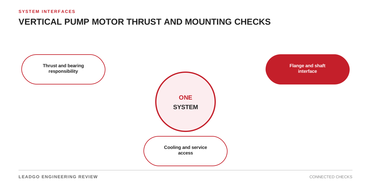
A vertical mounting code describes orientation; it does not prove that a motor can carry the pump’s axial load. Start with a combined pump–motor interface sheet, not motor kilowatts alone.
Decide who carries thrust
Ask for thrust at shutoff, rated flow, maximum flow and credible start, stop or reverse-flow events. Separate downthrust from upthrust and state whether shaft and coupling weight are included.
| Review item | Evidence required | Clarify when |
|---|---|---|
| Thrust responsibility | Sectioned load-path drawing | Each supplier assumes the other carries it |
| Load envelope | Up/down thrust by operating case | Only a normal-duty value is given |
| Bearing capability | Confirmation for load, speed and life basis | A generic bearing value is substituted |
| Lubrication/cooling | Method and site limits | Capability depends on unstated conditions |
Bearing approval must identify load direction, speed, duty and life criterion. A headline thrust number without these conditions is not transferable.
Close the mechanical interface
Overlay pump and motor drawings. Check flange face and pilot, bolt pattern, shaft extension, key, coupling hub position and the access needed to adjust shaft setting. Confirm rotor lifting or lowering steps and required bearing end play.
Check installation and cooling
Rain covers, pump heads and platforms can obstruct air. Record actual clearances and airflow direction. For outdoor service, define drain orientation, condensation protection and the storage period before commissioning.
Send the pump curve, thrust schedule, speed range, starting method, site ambient, mounting drawing and coupling data with the RFQ. Retain the approved interface drawing, bearing capability statement, shaft-setting procedure and installation inspection sheet.
Related reading: motor mounting arrangements and motor bearing selection.