
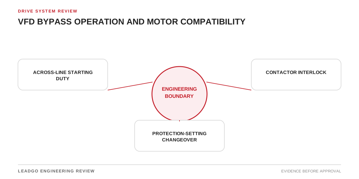
A bypass contactor does more than provide redundancy around a variable-frequency drive. It creates a second power path with different starting current, torque, speed control, protection and process behavior. Treating the bypass as a wiring accessory is a common reason for late commissioning changes.
The practical question is not whether the contactors can be energized. It is whether the complete motor system can start, run, stop and recover safely in every intended bypass state. This review converts that question into an evidence-based procurement and commissioning decision.
Applicability and operating boundary
Use this method for drive systems with manual, automatic or maintenance bypass, whether integrated in the VFD panel or assembled from separate switchgear. It applies to fixed-frequency bypass around low- or medium-voltage drives and to duties where continued operation after drive failure has commercial value.
It does not assume that bypass is always desirable. Some applications need controlled acceleration, reduced speed, reverse operation, torque regulation or process feedback that line operation cannot provide. Hazardous-area installations, fire-protection services, safety-related systems and medium-voltage switchgear may impose additional requirements. The project specification, authority requirements and selected equipment documentation control the final design.
Define the boundary from incoming supply through isolation, drive and bypass switching to the motor, driven equipment, field instrumentation and process controller. State whether bypass is intended for commissioning, emergency production, maintenance only or routine operation.
Bypass-readiness decision matrix
| Decision area | Evidence required | Ready condition | Blocker requiring action |
|---|---|---|---|
| Operating purpose | Approved bypass philosophy | Permitted users, duration and modes are defined | “Emergency use” has no operating definition |
| Supply capacity | Fault and starting study or justified assessment | Source and transformer tolerate bypass start | Voltage dip or generator loading is unknown |
| Motor starting | Motor current/torque curves and start limits | Across-line acceleration is demonstrated | VFD current limit was assumed in bypass |
| Driven load | Torque-speed curve and process start state | Load can start at line frequency | Process requires a ramp or unloaded start not provided |
| Motor speed | Nameplate frequency and process limit | Fixed bypass speed is acceptable | Overspeed or excessive process output is possible |
| Cooling | Motor cooling method and bypass duty | Cooling is adequate at bypass speed and load | Separate blower logic is not defined |
| Switching | Approved one-line and contactor ratings | Isolation and interlocking are suitable | Drive output can be connected to the line |
| Transfer | Control narrative and timing | Stop/restart or transfer method is defined | Reconnection to a spinning motor is unevaluated |
| Protection | Settings and device coordination for both paths | Motor protection remains effective in each mode | Drive protection disappears without replacement |
| Controls | I/O list, permissives and alarms | Mode indication and process commands are unambiguous | Controller cannot distinguish VFD and bypass |
| Safety | Lockout and local/remote provisions | Isolation points and stored-energy controls are clear | Maintenance can expose an energized alternate path |
| Acceptance | Functional test procedure | Every permitted transition is witnessed | Only contactor operation is tested |
One unresolved blocker is enough to hold bypass approval. The matrix prevents a mechanically complete panel from being accepted before system behavior is understood.
Check motor and load compatibility
Under VFD operation, current limit and acceleration ramp may keep electrical and mechanical stress below across-line values. In bypass, the motor sees the supply frequency immediately unless another starter is included. Verify starting current, available motor torque, load torque, inertia and permissible starting frequency using data for the offered motor and actual driven equipment.
Also compare the intended operating point. A fan or pump selected to run mainly below base speed may demand substantially different power at line speed. A conveyor may need a controlled ramp to avoid belt or product disturbance. A mixer may not tolerate starting with settled material. Bypass readiness therefore requires process evidence, not only a motor nameplate.
Confirm frequency and voltage compatibility. Do not use a dual-frequency nameplate as proof that the installed load can run at either speed. Check rotation, coupling and driven-equipment speed limits, lubrication, vibration and process capacity.
Define switching and transfer behavior
The fundamental interlock must prevent the bypass supply and VFD output from being connected together in an unintended state. Review mechanical and electrical interlocks, isolation, contactor utilization, short-circuit ratings and feedback contacts. Draw every power state rather than relying on a generic three-contactor diagram.
Decide whether the system always stops before changeover. A stop-and-restart strategy is often easier to verify, but the process must tolerate the interruption and restart. Transfer involving a spinning motor requires a specific engineering assessment of residual voltage, speed, phase relationship, delay, drive features and mechanical consequences. Do not improvise this behavior during commissioning.
Define the failure state. If the VFD fails, identify which auxiliary supplies, relays or controller signals remain available to command bypass. An automatic scheme is not resilient if the failed device owns the only permissive.
Protection in both power paths
Drive electronic protection may cover overload, phase loss, ground fault, stall and thermal modeling during normal operation. Those functions may no longer protect the motor in bypass. Map every required protection function to an active device in each mode.
Check overload sensing location, current-transformer ratios, short-circuit protection, earth-fault coverage, phase imbalance, locked rotor, temperature inputs and restart inhibit. If one relay uses separate setting groups, define the selection logic and fail-safe group. Ensure the bypass contactor and cables are rated for the available fault current and coordination basis.
Retain motor resistance-temperature detectors, bearing sensors, space heaters and separate blowers where required. Specify whether their alarms trip in both modes. A bypass designed only around three power conductors is incomplete.
Common design and commissioning mistakes
- Assuming a successful VFD start proves an across-line start.
- Sizing bypass components for running current without checking starting duty and fault rating.
- Allowing fixed line speed to exceed the process or driven-equipment limit.
- Omitting the high-load process state from the acceleration review.
- Depending on drive overload protection after the drive is isolated.
- Using controller software as the only barrier against simultaneous contactor closure.
- Failing to define behavior after loss and restoration of power.
- Leaving the separate cooling blower under a VFD-only command.
- Providing a selector switch without clear local, remote and maintenance authority.
- Testing individual contactors but not the permitted operating sequence.
Decision workflow
- Define why bypass exists and which operating modes are permitted.
- Confirm fixed-frequency speed and process output are acceptable.
- Demonstrate electrical and mechanical acceleration in the worst credible start state.
- Verify motor thermal duty and permissible start frequency.
- Review the complete one-line, isolation and interlock design.
- Select a documented transfer method, including spinning-motor restrictions.
- Map protection and monitoring functions for VFD and bypass modes.
- Freeze control permissives, alarms, mode feedback and operator authority.
- Perform a drawing-based failure review before energization.
- Witness functional tests and record settings, timing and unresolved limitations.
If the system cannot meet a row, alternatives include eliminating bypass, restricting it to unloaded maintenance operation, providing a reduced-voltage starter, modifying the process sequence or selecting equipment for the required duty.
Bypass package vendor return schedule
From the motor supplier, request rated and starting data, current-speed and torque-speed curves, inertia, permissible starts, thermal protection details, cooling requirements, sensor connections and confirmation of across-line suitability for the stated supply and load.
From the VFD or panel supplier, request one-line and elementary diagrams, interlock description, component ratings, fault withstand, transfer timing, control-power dependencies, protection functions in each mode, setting lists, software revision and factory test procedure. From the driven-equipment supplier, obtain torque-speed data, inertia, acceptable acceleration, maximum continuous speed, starting process state and operating restrictions.
The RFQ should state the bypass purpose and acceptance tests. Otherwise suppliers may price physically different concepts under the same word “bypass.”
Conditions for releasing bypass operation
Close bypass readiness only when the approved drawings match the installed equipment; source and motor studies support the start; fixed-speed operation is accepted by the process owner; motor and load limits are met; protection is active in both paths; interlocks prevent prohibited states; every permitted stop, start and transfer sequence passes a witnessed test; and operator and maintenance instructions identify restrictions.
Record relay settings, drive parameters, timers, selector positions, measured start behavior, alarm checks and test signatures. Label the panel to show alternate sources and isolation points. Keep any usage restriction with the operating procedure, not only in a design comment.