
Ask why a drive installation needs EMC work and the usual answer is that drives are noisy. True, and not useful. The specific thing a drive does that a sinusoidal supply does not is create a current with no return path inside the circuit, and almost every drive-related EMC symptom follows from where that current goes instead.
The two modes
| Differential mode | Common mode | |
|---|---|---|
| Path out | One conductor | All conductors together, same direction |
| Path back | Another conductor in the same circuit | Earth, shields, structure, whatever has lowest impedance |
| Disturbs | The circuit it belongs to | Everything sharing its return path |
| Fixed by | Filtering across the conductors | Controlling and bonding the return path |
Differential-mode current returns through conductors in the same circuit. Line reactors and differential-mode filters can reduce it, but the correct device and location depend on whether the disturbance is at the drive input or motor output.
Common mode is the one that causes arguments, because the current is not where anyone drew it. It left the drive on all three motor conductors at once and now has to get home through earth wiring, cable armour, the machine frame, the building steel, or a bearing.
Why a drive makes it and the mains does not
In the ideal balanced sinusoidal case, the three phase voltages sum to zero. A real winding neutral may float relative to earth and the supply may contain imbalance or harmonics, so earth potential should not be treated as an unconditional physical rule.
A drive does not do this. It switches each output between fixed DC rail levels, and at any given instant the three outputs do not sum to zero. MG 1 describes the consequence directly: these drives can generate a common-mode voltage that shifts the three-phase winding neutral potentials significantly from ground, oscillating at high frequency.
The standard also quantifies the related neutral shift. With some current-source inverters it can reach 2.3 per unit, producing motor line-to-ground voltages of up to 3.3 per unit. With a typical voltage-source inverter the line-to-ground magnitude can reach √3 times the crest of the nominal sinusoidal line-to-ground voltage. These are not small perturbations on top of a clean waveform.
Where the current actually goes
The winding is capacitively coupled to the frame and to the rotor. There is no component doing this, it is geometry: copper separated from steel by insulation is a capacitor, and at the switching frequencies involved its impedance is low enough to matter.
So the high-frequency common-mode voltage couples across to the rotor. MG 1 puts the result at pulses as high as 10 to 40 volts from shaft to ground, with the current path running through either or both bearings on its way to earth.
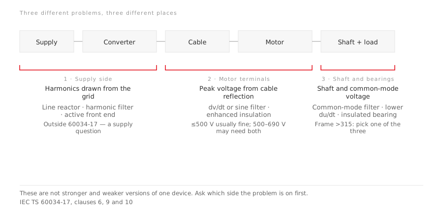
That is the mechanism behind the symptom everyone recognises. The hardware choices for fixing it are a separate question, and the first decision there is which side of the installation the symptom is actually on.
Two different shaft-voltage problems, often confused
MG 1 separates them, and the separation is worth keeping.
On a sinusoidal supply, shaft voltage comes from magnetic dissymmetries in the construction of the machine. It appears mostly in larger frames, usually 500 frame and larger, and produces an end-to-end shaft voltage. The current runs frame, bearing, shaft, other bearing, frame. Because the loop is closed through both bearings, insulating one of them interrupts it, and MG 1 gives a threshold: above 300 millivolts peak measured per IEEE 112, use bearing insulation.
On an inverter supply, the root cause is different. The common-mode voltage is capacitively coupled to the rotor and the current is trying to reach ground, not to circulate around a loop. Interrupting it requires insulating both bearings, and it appears in motors of all sizes rather than only large frames.
Same visible damage, different circuit, different fix. Treating an inverter-driven case with the sinusoidal remedy is how installations end up with one insulated bearing and a continuing problem.
What else shares that return path
Bearings get the attention because the damage is expensive and visible. The same current is responsible for the quieter complaints:
- Earth-leakage devices tripping for no load-side fault, because the common-mode current is a genuine earth current as far as the device is concerned.
- Instrumentation and 4-20 mA loops reading noise, where the signal cable shares a route or a ground reference with the motor cable.
- Encoder and fieldbus errors that correlate with drive switching rather than with mechanical events.
- Radiated emission from the motor cable, which becomes an antenna once common-mode current is flowing along it.
A site that blames four separate faults on four separate causes is often looking at one return path.
EMC compliance belongs to the installation
This is the part that surprises buyers. Under IEC 61800-3, a power drive system falls into categories C1 through C4, mapped to a first environment (residential and light industrial, sharing a supply with other consumers) and a second environment (industrial, with its own transformer).
The categories are not simply four rungs of one strictness ladder. They combine environment, intended user, voltage or current limits and the way the power drive system is placed on the market or incorporated into an installation. C4 addresses systems and fixed installations that fall outside the lower categories and relies on an EMC plan and engineering practice for the actual site. The exact category must be selected from the current edition of IEC 61800-3, not inferred from the word “industrial” alone.
A drive certified to a category is a component that can meet that category. Whether the installation does depends on the cable, its shield, how the shield is terminated, the bonding, and the separation from signal routes. Nobody can ship you compliance in a box.
What the standard admits it cannot tell you
MG 1 is unusually candid here, and it is worth quoting the position rather than pretending to more certainty. It records that no conclusive study has quantified the relationship between peak voltage from inverter operation and bearing life or failure, and that there is no standard method for measuring this voltage. Its conclusion is that the potential for problems cannot consistently be determined in advance of installation.
Two things follow. Anyone offering a confident prediction of bearing life from drive parameters is going beyond what the standard supports. And the sensible response is to design the return path well rather than to calculate whether you can get away with not doing so.
What to do about it
- Follow the drive manufacturer’s EMC installation instructions for cable type, allowable length, shield termination and filters. A symmetrical shielded motor cable with full-circumference termination at both ends is a common arrangement, but equipment-specific instructions govern.
- Bond the motor frame and drive enclosure with a low-impedance high-frequency path while preserving the required protective bonding. EMC bonding does not replace the protective conductor.
- Keep signal and motor cables apart, and cross them at right angles where they must meet.
- Deal with the current at the source with a common-mode choke or output filter when the installation is long or sensitive.
- Remember that insulating motor bearings protects the motor and not the gearbox on the other side of the coupling.
When you order the motor, send the converter type, the switching frequency and the cable length with the enquiry. Those three decide the terminal voltage and the derating, and a motor maker who is given them can answer properly rather than quoting a general-purpose machine and hoping. LEADGO’s inverter-duty induction series is specified against those inputs for that reason.
Related: VFD ancillaries: which side is the problem · Flameproof motors rated for inverter supply · Sensorless control: when you can skip the encoder · Testing motor efficiency on an inverter supply