
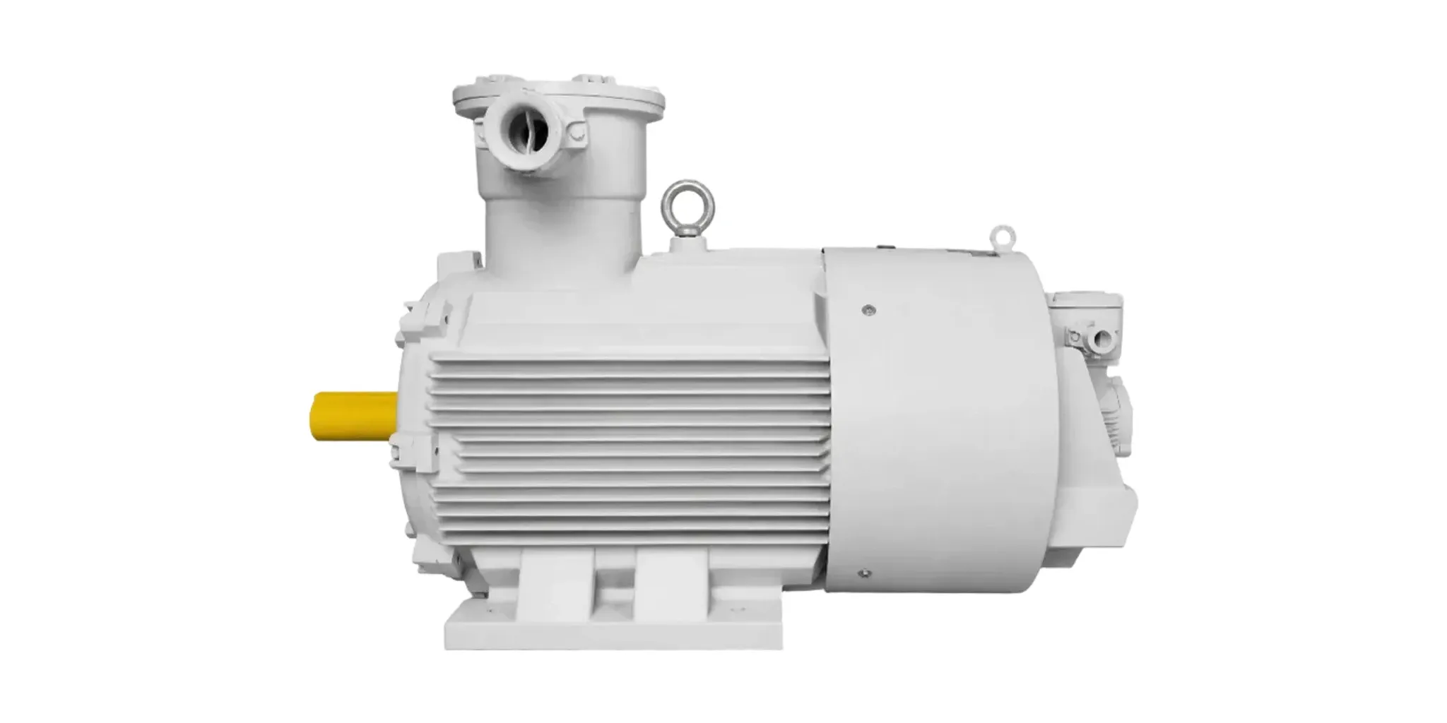
“Can I run a flameproof motor on a drive?” is asked as a yes/no question. It has a yes answer, a product standard behind it, and a set of numbers that decide whether the installation actually works.
Direct answer
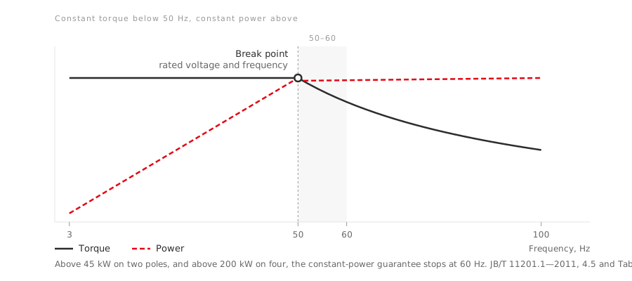
Yes. JB/T 11201.1—2011 covers flameproof variable-frequency three-phase induction motors in frames 80 to 355, and it states what the machine guarantees:
- Constant torque from 3 Hz to 50 Hz
- Constant power from 50 Hz to 100 Hz
That is the headline. The rest of this article is the part that decides projects.
What “rated frequency” actually points at
The standard carries a short note under its voltage and frequency clause that is worth reading twice:
Rated voltage and rated frequency refer to the working voltage and frequency at the break point between the motor’s constant-torque and constant-power characteristics.
So 50 Hz on an inverter-duty nameplate is not the top of the range. It is the corner where the machine changes behaviour — below it, torque is held and voltage rises with frequency; above it, voltage is held, flux falls, and power is held instead.
A specification that treats the nameplate frequency as a maximum has misread the machine in a way that costs available speed. One that treats it as a mid-point without checking the upper window has the opposite problem.
The upper window narrows with size
This is the number most often assumed rather than looked up. The constant-power range is not 50–100 Hz for everything:
| Machine | Constant-power range |
|---|---|
| Two-pole, 45 kW and below | 50 Hz – 100 Hz |
| Two-pole, above 45 kW | 50 Hz – 60 Hz |
| Four-pole, above 200 kW | 50 Hz – 60 Hz |
| Otherwise | 50 Hz – 100 Hz |
If an application depends on running above base speed — and many fan and pump retrofits do — then rating and pole count decide how much headroom exists before the guarantee stops. Finding that out after the drive is specified is an expensive way to learn it.
Cooling is where inverter duty is actually different
The standard lists two cooling methods for this series: IC411 and IC416, the second being forced ventilation.
The reason matters more than the code. A shaft-mounted fan turns at rotor speed, so it slows down exactly as the machine slows. On a constant-torque load held at 5 or 10 Hz, the motor may still be delivering full torque — and therefore producing close to full loss — while its own cooling has almost stopped. IC416 separates the two by driving the fan independently.
The standard’s own test procedure makes the distinction visible: after the temperature-rise run, the motor is stopped immediately but the fan is required to keep running while the winding resistance and bearing temperatures are taken.
That single sentence is the clearest statement of what inverter duty changes. It is not primarily an electrical problem. It is a cooling problem.
What the load characteristic test actually does
Buyers asking for “the VFD test report” often do not know what is in it. For this series the load characteristic determination is specified in detail:
- Set the drive to 3 (or 5) Hz, 15 Hz, 30 Hz and 50 Hz, and at each frequency measure torque at rated torque, 110% of rated torque, and 80% of rated torque.
- Then at 60 Hz, 80 Hz and 100 Hz, measure torque at nominal power, 110% and 80% of nominal power.
- Plot the load characteristic curve from those points.
- Throughout the test, the motor shall run smoothly, with no obvious torque pulsation.
That last condition is an acceptance criterion, not a description. It is also the one a curve on a datasheet does not show you — which is why the report is worth asking for rather than the curve alone.
The marking has a ceiling on this series
Worth knowing before a hazardous-area specification is written against it. The Ex markings this standard provides for are:
- Ex d I Mb — mining firedamp
- Ex d IIA T1–T4 Gb and Ex d IIB T1–T4 Gb
There is no IIC in that list. A site classified IIC — hydrogen or acetylene — is outside what this series is built to, and no amount of drive configuration changes that. The subgroups run one way only; see gas and dust subgroups explained.
Enclosure protection is IP55, and the rating is based on continuous duty S1.
The documentation rule that closes the loop
There is a requirement in the general explosion-protection standard that answers the original question properly, and almost nobody cites it.
GB/T 3836.1—2021 clause 30.3 requires motor instructions to include, where applicable, a speed/torque curve for inverter-fed machines. And for increased-safety motors type-tested together with an inverter, the instructions must also state the inverter parameters used in that type test — rated motor current, weighted total harmonic distortion or pulse frequency, and DC-link voltage — expressly so that a similar inverter can be selected.
Read that as the answer to “can I run this on a drive”: the documentation is supposed to tell you which drives the certification covers. If it does not, nobody has established it yet, and that is a different situation from the machine being unsuitable.
What to ask for
- The two frequency ranges for your specific rating and pole count — not the series headline.
- The cooling method — IC411 or IC416 — and, if the load holds torque at low speed, why IC411 would be sufficient.
- The load characteristic report, including the smooth-running assessment.
- The Ex marking, checked against your subgroup rather than against the series.
- The inverter parameters from the type test, if the machine was type-tested with one.
LEADGO builds the YBBP flameproof variable-frequency series to this standard. Send the load’s torque requirement at its lowest running speed — that number, not the power, is what decides whether IC411 will do.
Going deeper
- Drive system efficiency: IE for the motor, IES for the system — how a converter-fed machine’s efficiency class is established, and why it is measured at 90% of rated speed
- Motor temperature classes T1 to T6 — why anything raising surface temperature on a flameproof machine attacks a certified specification
- How to verify an explosion-proof motor certificate — including the special conditions of use that may apply to inverter operation