
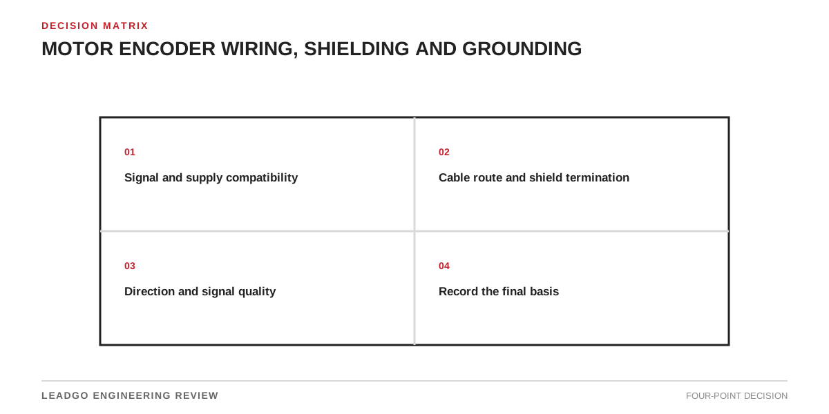
Encoder faults often originate in cabling rather than the sensor. Pair allocation, shield termination, isolation, connector pinout and separation from motor leads determine whether pulses reach the drive without common-mode interference.
Preserve the encoder signal path
ABB calls for double-shielded encoder cable and varies termination according to whether the encoder is isolated from motor and earth. That decision must be taken from the exact interface-module and encoder manuals, not a universal one-end rule.
Signal path
| Item | Engineering purpose | Review action |
|---|---|---|
| Differential pairs | Matched signal and return | Preserve twist to terminals |
| Cable shield | High-frequency noise return | Follow module and encoder instructions |
| Isolation | Motor-to-encoder relationship | Avoid unintended loops |
| Route | Distance from power cable | Reduce inductive coupling |
Evidence required before approval
Test supply voltage at the encoder, channel phasing, direction, zero-speed stability and feedback under loaded operation. Save scope traces when intermittent noise is suspected.
Retain the equipment revision and test record. Name the reviewer. Keep open assumptions visible.
Commissioning decision
Never approve a copied setting. Confirm interface compatibility and operating limits. Exercise the intended response during a functional test.