
Someone reports a problem on a drive installation and the answer arrives as a shopping list: add a line reactor, add a dv/dt filter, insulate the bearings. Those three things do not do the same job, and two of them will be money spent on the wrong end of the installation.
Direct answer
There are three distinct problems, and they live in three different places.
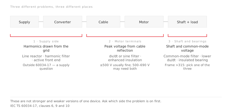
| Where | What goes wrong | What addresses it | |
|---|---|---|---|
| 1 | Supply side | Harmonics drawn from the grid | Line reactor, harmonic filter, active front end |
| 2 | Motor terminals | Peak voltage from cable reflection | dv/dt or sine filter, enhanced insulation |
| 3 | Shaft and bearings | Shaft voltage and common-mode voltage | Common-mode filter, lower du/dt, insulated bearing |
None of these substitutes for another. A line reactor does nothing about the voltage arriving at the motor terminals; a filter at the converter output does nothing about what the drive is doing to the supply.
And there is a fourth thing that is not hardware at all — the motor’s own derating. That one is settled on paper, before anything is bought.
Before hardware: the motor is already giving up torque
When a motor is supplied from a converter at rated frequency, the available torque is usually less than the rated torque on a sinusoidal supply. Two things cause it: the temperature rise from the additional losses, and the ratio of the converter’s output voltage at the motor’s rated frequency to the motor’s rated voltage.
The application guide puts a number on it:
The derating factor at rated frequency typically ranges from 0.8 to 1.0.
Which end of that range you land on depends on the individual motor design, on the cooling arrangement, and on the thermal reserve the particular machine has. A self-cooled machine and a separately ventilated one do not behave the same here — see what TEFC actually means for why IC411 and IC416 diverge on a drive.
The part worth carrying into an enquiry is this:
A derating curve can be declared by the motor manufacturer — if the harmonic spectrum and the voltage-frequency characteristic of the converter are known.
So the question “how much torque will I actually get” is answerable. It is just not answerable from a motor datasheet alone, because half the input is the converter. That is the practical reason the motor and the drive are one specification rather than two purchases.
Above the rated point the machine enters field weakening, where the converter output voltage stays constant as frequency rises and torque capability falls away rapidly — the shape set out in constant torque and constant power.
Side 2: the voltage that arrives is not the voltage that left
Fast switching plus a cable produces peak voltages at the motor terminals through transmission line effects — the pulse reflects at the motor end and adds to the incoming one. The cable is not a neutral conductor between the two devices; it is part of the circuit that determines the stress.
The guide draws a line by rated voltage:
- At 500 V a.c. and below, the insulation system should typically give satisfactory life at the peak voltages involved.
- Over 500 V up to 690 V, fed from a fast-switching inverter, an enhanced insulation system and/or filters designed to limit the rise time and/or the peak voltages may be required.
Note what defines “fast”: the rise time is the interval during which the voltage changes from 10 % to 90 % of the whole voltage range. It is the steepness of the edge, not the switching frequency, that stresses the first turns of the winding.
The guide’s own conclusion on this point is a caution against treating it as a catalogue problem: given the complex interrelations, it suggests careful design of the complete drive, and notes that filters at the converter output are sometimes necessary.
Side 3: bearing currents, and the frame size that decides
This is the one most often bought blind, and the guide is unusually specific about when it matters.
Two different voltages cause bearing currents, and they are not the same phenomenon:
- Shaft voltage is induced in the loop made up of the shaft, the bearings, the end shields and the housing, by a ring flux in the stator yoke. Irregularities in the yoke cause that flux — dovetailed punchings that clamp the core, ventilation ducts, magnetic anisotropy in the laminations. A zero-sequence component in the stator currents can increase it, and how large that is depends on the earthing system.
- Common-mode voltage is inherent to the control algorithm of a PWM converter. A proportion of it appears across the bearing itself.
Measured bearing voltage is typically 10 V to 30 V peak. The guide also records a negative result worth knowing: an interrelation between circulating currents and bearing voltage could not be recognised — so one does not predict the other.
Then the decision rule, which is about frame size:
| Machine | What the guide says |
|---|---|
| Frame ≤ 315 | Seldom experiences bearing failure caused by converter operation |
| Frame ≤ 315, converter above 10 kHz pulse frequency and above 400 V r.m.s. output | Consider bearing insulation |
| Frame > 315 | Use one of: a converter with a filter reducing the common-mode voltage; a reduced du/dt; or insulated bearings |
Read the last row carefully — it is one of three, not all three. Two of the three options are properties of the drive, not of the motor, which is why this cannot be settled by the motor supplier alone.
On insulating bearings: the method is to replace the bearing with an insulated one of the same dimensions. Insulating both bearings is seldom necessary, and where it is done the guide recommends an expert examine the whole drive system — including the driven machine, where the coupling may need insulating, and the grounding system, where an earthing brush may be needed. Insulate both ends without looking at the rest of the train and the current finds another path.
What to send when you ask
Because half the answer lives in the converter, an enquiry that names only the motor cannot be answered properly:
- Converter make, model and rating — and whether it is a voltage-source or current-source type.
- Pulse frequency and output voltage, which set the bearing-current question.
- Cable type and length between converter and motor, which set the reflection question.
- Motor rated voltage — the 500 V and 690 V lines above.
- Frame size, which decides whether bearing measures are recommended at all.
- Speed range and load type, so the derating can be worked at the operating point rather than only at rated frequency.
- Earthing arrangement, because the zero-sequence path depends on it.
With those, a derating curve and a bearing recommendation are both answerable. Without them, any answer is a guess wearing a part number.
LEADGO’s inverter-duty and variable-frequency series — including the flameproof variable-frequency machines, where the drive interaction is a certification question as well as a life question — are specified against the converter rather than in isolation. Send the seven items above with the enquiry and the reply can include the derating, rather than a datasheet that assumes a sinusoidal supply.
⚠ The application guide cited throughout is the 2002 edition; a later edition exists, so quote the edition when you cite a figure from it.
Going deeper
- Flameproof motors on a VFD — where the same interaction becomes a certification question
- What TEFC actually means — IC411 versus IC416, and why the cooling arrangement decides the derating
- Why oilfield motors run hot — the third path, where a drive was added without matching the cooling
- From zone to motor — the installation standard’s own clause on converter-fed machines in hazardous areas