
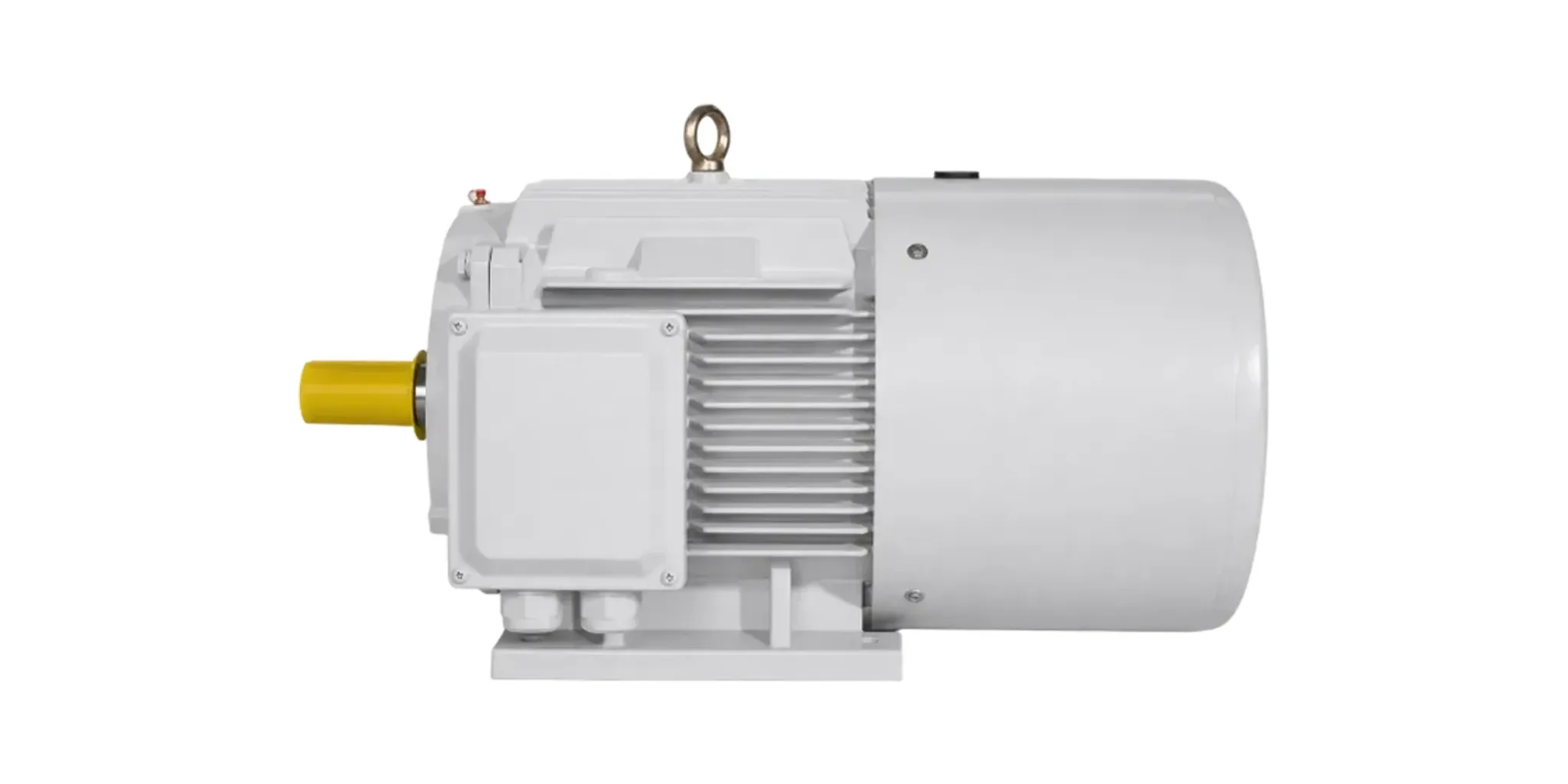
Most motor specifications describe what a machine does while it is running. A brake motor is specified mostly around what happens when it stops — and, more precisely, around what happens when it stops without being asked to.
Direct answer
An electromagnetic brake motor is fail-safe by construction: the electromagnet releases the brake, so removing the supply applies it. The brake holds the load when the power is gone.
Two things follow that are easy to state and easy to forget:
- The brake is a safety device, not a feature. It is doing its most important work at the moment when nothing else on the machine is working.
- Because releasing takes electrical energy, anything that delays the collapse of that energy delays the brake. Which brings us to the wiring.
The wiring decision that decides braking time
The brake coil is a DC electromagnet fed through a rectifier. That means there are two places to break the circuit, and they do not behave the same way.
Switch the AC side only, and the coil is left to discharge through its own inductance. Current decays slowly, the magnet stays pulled in, and the brake stays released for an appreciable time after the command. The motor has stopped driving; the brake has not yet started holding. On a hoist the load keeps descending through that window. On a positioning drive the axis overshoots.
Switch the DC side, and the field collapses quickly.
This is not a refinement — the product standard builds it into the measurement. In the braking-time test of JB/T 6456—2022, the brake excitation supply is required to be cut on the DC side at the same moment as the motor supply. The published braking time belongs to that wiring. Install the same motor with AC-side switching only and the number on the datasheet is no longer the number you get.
So the specification line is short and worth writing explicitly: where the motor has to brake quickly, the brake is to be switched on its DC side, wired to the diagram in the terminal box.
What the standard makes the manufacturer tell you
JB/T 6456—2022 requires four brake quantities to be declared, and defines how each is measured:
| Quantity | How it is established |
|---|---|
| Static braking torque | A lever is fixed to the shaft extension and a force applied at a known distance through a spring balance; the reading at the instant of slip, corrected for the lever’s own weight, gives the torque |
| No-load braking time | Measured with the excitation cut on the DC side simultaneously with the motor supply |
| Excitation power | The product of the average DC excitation voltage and the average excitation current, both measured with DC instruments |
| Maximum working air gap | Specified by frame size — a wear limit, not a set-up tolerance |
If a quotation gives you a brake torque and nothing else, three of the four are missing — and the missing ones are the ones that tell you how the brake behaves over its life rather than on day one.
The test that answers “will it still work in year five”
Annex A.4 is the clause worth knowing about, because it stacks two degradations that real installations experience separately and eventually experience together:
- The armature-to-core air gap is set to its maximum permitted value — that is, the brake is treated as worn.
- The excitation voltage is reduced to 85% of rated — that is, the supply is treated as weak.
With both conditions applied at once, the motor must start and brake normally at no load.
That is a far more useful number than a brake torque measured on a new machine at nominal voltage. A long cable run to a crane, a site with a soft supply, a brake three years into its friction disc — the standard has a test for that combination, and it is reasonable to ask whether a particular machine passed it.
The air gap is the wear item
As the friction disc wears, the gap the electromagnet has to close grows. Magnetic pull falls off sharply with distance, so a brake that releases crisply when new can become sluggish, and eventually fail to release at all, without anything else changing.
This is also why bearing condition and brake condition are linked on these machines. A bearing that is allowed to run on until it seizes lets the rotor touch the stator — and on a brake motor the brake gap goes out of adjustment along with it. The bearing temperature limit on this series is 95 °C by thermometer; the insulation resistance limit, hot or after a heat run, is 0.38 MΩ — and that applies to the brake excitation coil as well as the stator winding, which is the check most commissioning routines forget.
Manual release is an option, and a hazard
JB/T 6456—2022 puts it plainly: the brake shall have a reliable manual release device where the user has a special requirement. It is not assumed to be fitted. If maintenance procedures depend on being able to release the brake by hand, that has to be on the order.
And it carries its own risk. A brake motor can be moved by the load it holds once the brake is released by hand — releasing the brake on a suspended load lets that load move. Isolation and mechanical securing come first, every time.
Duty: these are not S1 machines
Brake motors live on hoists, cranes, positioning drives and cycling conveyors, which means starting and braking heat is part of what the machine has to dissipate. That is S4 and S5 territory — intermittent periodic duty including starting, and including electric braking — not continuous duty.
If the duty is not stated on the enquiry, the manufacturer is required to assume S1, which is the wrong basis for every application listed above. See motor duty types S1 to S10.
What the 2022 revision changed
The current edition replaced JB/T 6456—2010, and the changes are the kind that matter when comparing an old quotation with a new one:
- Degree of protection in the title moved from IP44 to IP55.
- Frame range widened from 80–225 to 63–280.
- Power range widened to 0.12 kW to 90 kW.
- Maximum working air gap values added for the new frame sizes.
- A requirement for the interval after switch-off was added, and the manual-release clause was revised.
If a datasheet or manual still cites the 2010 edition, that is worth querying — not because the motor is wrong, but because the documentation and the machine may be describing different editions.
What to ask for
- Static braking torque, and whether it was measured per the standard’s method.
- No-load braking time, and confirmation that it was measured with DC-side switching.
- Excitation voltage and power, so the control circuit can be designed around it.
- Maximum working air gap, so maintenance has a wear limit to inspect against.
- Manual release, if you need it — it is not assumed.
- The duty type, stated explicitly, because the default is wrong here.
LEADGO’s YEJ series is built to this standard across frames 63 to 280. Send the duty cycle and say whether DC-side switching is required — those two lines change the machine more than the power rating does.
Going deeper
- Motor duty types S1 to S10 — where S4 and S5 are defined, and what has to be quoted with them
- Motor IP ratings: what each digit is actually tested for — the IP44-to-IP55 change above, and what it actually buys
- NEMA MG 1 explained — the parallel US standard, for comparing a brake motor across systems