
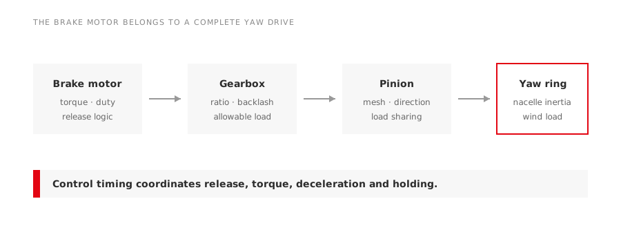
A yaw motor does not merely turn a nacelle. It works through a gearbox against wind load, starts and stops repeatedly, coordinates with several drives and usually carries a brake whose job must be defined precisely.
Direct answer
Select a yaw-drive brake motor from the complete drive chain:
motor → brake → gearbox → pinion → yaw ring → nacelle
Rated power and speed are only the beginning. The enquiry also needs output torque, gear ratio, number of drives sharing the load, acceleration and stopping sequence, brake function, starts, ambient, mounting and control feedback.
Define what the brake does
An electromagnetic brake may be used to hold the shaft after positioning, contribute to stopping, control backlash or provide a defined response after loss of power. These duties create different thermal and torque requirements.
Ask four questions:
- Is the brake primarily a holding brake, a dynamic stopping brake or both?
- At what shaft speed may it engage?
- How much kinetic and external-load energy must it absorb?
- How often does the sequence repeat?
If the VFD or contactor normally decelerates the motor before the brake sets, the delay time matters. If the brake closes too early, it can absorb unintended energy and wear rapidly. If it closes too late, the drive can move after the stop command.
The motor sees an intermittent mechanical duty
Yaw drives may remain stopped for long periods and then make a sequence of corrections. Average power can look modest while starting torque, acceleration time and starts per hour set the thermal requirement.
| Duty input | Why it matters |
|---|---|
| Starts and stops per hour | Winding and brake heating |
| Maximum correction duration | Motor temperature accumulation |
| Number of simultaneous drives | Load sharing and control coordination |
| Nacelle inertia and wind load | Acceleration and stopping torque |
| Gear efficiency and backlash | Required motor torque and positioning behaviour |
| Emergency sequence | Brake energy and fail-safe response |
Provide both normal and worst credible operating sequences. A continuous-duty catalogue rating alone does not describe them.
Match the gearbox interface
Replacement enquiries should include flange register, bolt circle, shaft diameter and length, key, allowable radial/axial load, mounting position and mass. Gearbox input speed and permissible torque must agree with the motor.
Direction of rotation is also a system matter. Swapping two phases changes motor direction but can conflict with encoder logic, limit switches or the intended action of a backstop. Commissioning must confirm commanded direction at low-risk conditions before normal operation.
Electrical data beyond the main nameplate
Record motor voltage, frequency, current, connection, supply method and thermal protection. Then capture the brake separately:
- brake torque and permissible wear range;
- coil or rectifier input voltage;
- AC- or DC-side switching arrangement;
- release and engagement timing;
- manual-release provision;
- air-gap inspection and adjustment method;
- heater or anti-condensation provision.
The brake rectifier may sit inside the terminal box or in the control cabinet. Replacing it with a visually similar part can change release time and coil voltage.
Environment is unusually important
The nacelle sees temperature cycles, condensation, vibration and difficult access. Offshore or coastal service adds salt exposure. Dust, oil mist and water ingress can affect friction surfaces and electrical insulation.
Specify ambient range, altitude, humidity/condensation conditions, corrosion category required by the project, enclosure protection, cable-entry direction and coating system. Confirm that drain plugs and breathers remain correctly positioned after mounting.
Cold conditions deserve a separate review. Grease viscosity, brake release, seals and gearbox losses can change the starting requirement. The manufacturer should evaluate the complete low-temperature package rather than approve the motor from winding insulation alone.
Control and feedback belong in the enquiry
List encoder or resolver type, supply, signal interface, connector, pulse count or absolute protocol, and mechanical mounting. Include thermal sensors and brake-status switches.
The control sequence should define:
- brake release command;
- confirmation or release delay;
- motor torque enable;
- controlled deceleration;
- brake application;
- torque removal;
- fault response if release or stopping is not confirmed.
These timings must follow the turbine and drive-system design. They should not be improvised from a generic brake-motor manual.
Replacement survey
Before removal, collect:
- motor, brake, gearbox and encoder nameplates;
- dimensioned photos from all sides;
- terminal connections and rectifier wiring;
- mounting, shaft and flange measurements;
- brake air gap and wear condition;
- operating current and fault history;
- start/stop timing and control drawings;
- evidence of water ingress, overheating or uneven load sharing.
LEADGO’s YEJ electromagnetic brake motor range is one possible product family; final suitability depends on the turbine’s approved mechanical and control requirements.