
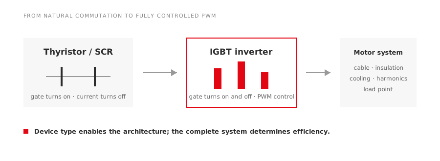
Modern variable-frequency drives are often described as more efficient simply because they use IGBTs. That explanation is incomplete. The important change is that the power switch became fully controllable, which allowed a different converter architecture, faster protection and much finer control of the motor waveform.
Understanding that change helps buyers evaluate a retrofit without treating every old drive as wasteful or every new one as automatically superior.
What a thyristor can and cannot do
A conventional silicon-controlled rectifier, or SCR, is a latching device. A gate pulse turns it on. In an AC circuit it normally turns off when current naturally crosses zero and falls below the holding current. This makes an SCR very effective for phase-controlled rectifiers, voltage controllers and soft starters.
The limitation appears when the converter needs to create a rapidly changing output waveform. The gate cannot simply command an ordinary SCR off at any desired instant. Additional commutation circuitry or a different device is required. Older variable-speed systems therefore tended to use more complex power stages, lower switching rates or motor technologies suited to the available converter.
This does not make the thyristor obsolete. High-power rectifiers and soft starters still use it well. It means that its strengths do not match every task performed by a modern PWM inverter.
What the IGBT changed
An insulated-gate bipolar transistor can be commanded on and off through its gate. The drive can therefore switch the DC-link voltage across the motor phases many times during each electrical cycle. Pulse-width modulation controls the average phase voltage while the switching sequence establishes output frequency.
That control brings several practical gains:
- output frequency can change smoothly over the permitted speed range;
- current can be regulated cycle by cycle;
- vector-control algorithms can manage flux-producing and torque-producing current separately;
- faults can be detected and interrupted quickly;
- the converter can be built as a compact rectifier, DC link and inverter package.
The motor still sees a pulsed waveform, not a laboratory sine wave. Fast voltage edges, common-mode voltage and reflected-wave effects remain engineering issues. A newer semiconductor solves the switching problem; it does not remove the need to match the drive, cable and motor.
Where the efficiency improvement comes from
Efficiency changes in more than one place. Device conduction losses matter, but so do switching losses, passive components, cooling power and the motor’s harmonic losses. A modern drive may also operate the motor closer to the required process point instead of wasting energy across a valve, damper or mechanical control.
The largest project saving frequently comes from speed control rather than from a small difference in converter efficiency. On a variable-torque load such as a centrifugal fan or pump, reducing speed can reduce process power sharply. On a conveyor requiring nearly constant torque, the saving pattern is different.
This distinction matters in quotations. Ask whether a claimed saving refers to:
- converter efficiency alone;
- motor efficiency with the converter;
- the complete driven system; or
- a process change caused by running at a different speed.
Those figures are not interchangeable.
Switching faster also has a cost
Higher switching frequency can improve current waveform quality and reduce audible motor noise. It also increases switching loss in the power devices and can raise thermal stress inside the drive. Manufacturers balance acoustic performance, current ripple, device temperature and motor requirements when setting the carrier frequency.
Long motor cables add another constraint. Fast voltage transitions can produce reflected-wave overvoltage at the motor terminals. Cable type, length, grounding and the motor insulation system may lead to an output reactor, dV/dt filter or sine-wave filter. Our guide to matching a VFD to a motor explains these checks as a system decision.
A practical replacement checklist
Before replacing an older converter, record the driven load and the behavior that must be preserved. Include starting torque, minimum continuous speed, acceleration time, braking or regeneration, overload duration and any encoder feedback.
Then verify:
- incoming voltage, frequency, short-circuit level and harmonic limits;
- motor rated current, insulation suitability and cooling at low speed;
- cable length and installation method;
- required control mode and speed accuracy;
- braking resistor, regenerative unit or common DC-bus requirement;
- environmental temperature, dust, corrosion and enclosure rating;
- communications and safety functions;
- access to parameters, backups and replacement parts.
An IGBT is an enabling component, not the whole specification. The reliable retrofit is the one that reproduces the required torque-speed behavior, protects the existing motor and fits the electrical installation.
Why waveform quality matters to the motor
An older phase-controlled system and a modern voltage-source PWM inverter can impose very different electrical stress even when both produce the same average shaft speed. Harmonic current adds motor heating. Fast common-mode voltage can drive current through bearings or connected machinery. Repeated steep-front pulses can stress the first turns of a winding, especially with a long cable and an unfavorable impedance match.
These effects do not mean PWM should be avoided. They mean the retrofit scope must extend to the motor terminals. Confirm the motor’s inverter-duty insulation, permissible carrier-frequency range, cable length and grounding. Check whether insulated bearings, a shaft-grounding arrangement or an output filter is required. If the motor is old or its winding history is unknown, an insulation assessment before commissioning is more useful than assuming that a lower rated current guarantees safety.
Input-side behavior matters too. A diode-front-end VFD, an active front end and an older controlled rectifier present different power factor and harmonic characteristics. Review the facility’s harmonic limits, transformer loading and power-factor correction equipment. Capacitor banks should not be left in a configuration that can resonate with the new converter.
The useful conclusion
The move from thyristor-dominated control to IGBT PWM drives changed what an AC motor system could do. Fully controlled switching made precise current regulation, compact inverters and advanced motor control practical. Buyers still need to judge the complete drive system. Efficiency, reliability and motor life come from the topology, application and installation working together.