
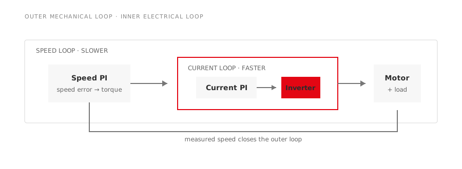
A speed-controlled motor looks like one task: compare commanded speed with actual speed and correct the difference. Inside a modern drive, that task is normally divided between at least two controllers. A fast current loop sits inside a slower speed loop.
This architecture is not unnecessary complexity. It separates electrical torque production from mechanical motion and gives the drive a place to enforce current limits before a speed error becomes damaging.
Start with torque
Motor speed changes only when electromagnetic torque differs from load torque and losses. Current is the drive variable most directly connected to electromagnetic torque. In a DC motor this relationship is intuitive; in vector-controlled AC drives, the controller transforms measured phase currents into components associated with flux and torque.
The inner loop regulates those current components. It reacts on the electrical time scale set by motor resistance, inductance, inverter switching, sampling and calculation delay. Its jobs include:
- following the torque-producing current command;
- rejecting fast electrical disturbances;
- limiting current during acceleration or a load step;
- supporting flux control and decoupling;
- providing a predictable torque actuator for the outer loop.
If this loop is poorly tuned, the motor cannot produce the commanded torque cleanly. Speed-loop changes will only disguise the problem temporarily.
What the speed loop does
The outer loop compares speed reference with measured or estimated speed. Its output is usually a torque or torque-producing current request. When the load increases and speed falls, the controller requests more current. When the load drops, it reduces the request.
Mechanical dynamics are slower because they include combined inertia, coupling compliance, friction and the driven machine. The speed loop therefore does not need to react as fast as the current loop. Trying to make it equally fast removes the separation on which the cascade depends.
This also explains why two machines using the same motor and drive may need different speed-loop settings. A direct-coupled pump, a high-inertia fan and a reciprocating pumping unit present different mechanical plants even when motor nameplates match.
Why the loops are nested
Consider a sudden speed command. The speed controller sees a large error and requests torque. The request passes through a current or torque limit before reaching the inner loop. The current loop then raises motor current as quickly as permitted. As the motor accelerates, the speed error falls and the outer controller reduces the request.
Without the inner loop, the speed controller would have to manage the motor’s electrical dynamics, inverter delay and mechanical dynamics at once. It would also need to prevent destructive current while chasing speed. The nested design assigns each job to the variable that reveals it most directly.
| Control layer | Main input | Main output | Primary concern |
|---|---|---|---|
| Current loop | Current error | Inverter voltage command | Torque response and current protection |
| Speed loop | Speed error | Torque/current request | Speed accuracy and load rejection |
| Position loop, when used | Position error | Speed request | Motion and positioning |
A servo drive may add a still slower position loop outside the speed loop. The same principle applies: faster inner behavior must be established before a slower outer objective is closed around it.
Limits are part of the control structure
The speed controller cannot be allowed to demand unlimited current. Its output is clamped to the permitted motoring and regenerative torque. Acceleration and deceleration ramps may further shape the command. Voltage limitation becomes important near base speed and in field weakening.
When a limit is active, the controller should prevent integral windup. Otherwise, speed error continues accumulating in the integrator even though additional torque is unavailable. The stored command then produces overshoot when the machine leaves saturation.
Repeated operation at current limit can indicate an aggressive ramp, insufficient motor torque, excessive load, low supply voltage or a mechanical fault. Raising the limit before identifying the cause risks moving the problem into the motor or inverter.
Commission in the right order
Commissioning should proceed from the inside out:
- verify current sensors, phase order and motor parameters;
- identify the motor where the drive procedure requires it;
- tune or validate the current loop;
- confirm current limiting and anti-windup behavior;
- enter inertia and mechanical data;
- tune the speed loop at a lower bandwidth;
- test realistic acceleration, load disturbances and stopping;
- validate operation at minimum speed, base speed and any field-weakening range.
The article on PI controller tuning describes how model-based starting gains fit this sequence. Do not copy gains from an unrelated machine merely because its motor power is similar.
What common symptoms suggest
A high-frequency current oscillation with relatively steady speed points first toward the current loop, sampling, motor parameters or measurement noise. A slower speed hunt with cyclic current command often points toward the speed loop or mechanical load. Oscillation at one narrow speed may be a structural resonance rather than either PI controller alone.
On a pumpjack, compressor or other pulsating load, speed can remain within tolerance while current varies widely through the cycle. That is expected only within the motor, drive and thermal limits. Trend current, torque command, speed and limit status together.
What buyers should request
For a packaged motor-drive system, ask the supplier to state the control mode, feedback method, speed range, continuous and short-time torque, current limit, overload duration and commissioning responsibility. A claim such as “vector control” does not show that the two loops have been validated for the actual load.
The useful proof is a trace from the application or a representative test showing speed, current and limit behavior during the difficult event: starting, a load step, low-speed operation or controlled stopping.
Nested control works because each loop has a clear job and a distinct time scale. Current control makes torque fast and safe. Speed control turns that torque into the required mechanical behavior. Keeping that hierarchy intact is the foundation of a stable drive.