
A permanent-magnet motor can keep running after part of its rotor flux has been lost. That is what makes demagnetization different from an open circuit or a seized bearing: the first symptom may be a gradual need for more current to produce the same torque, not a clean stop.
The useful question is therefore not “What temperature destroys a magnet?” It is “Under the worst rotor temperature and opposing magnetic field this drive can create, does the magnet operating point remain above the knee of its demagnetization curve?”
Direct answer
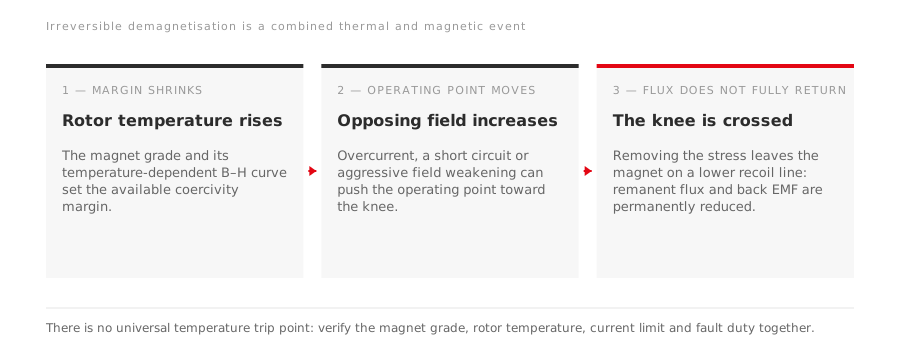
Demagnetization becomes irreversible when the magnet’s operating point crosses the knee of its temperature-specific B–H curve. Before that point, some flux reduction can be reversible: remove the opposing field or let the magnet cool, and most of the flux returns. Beyond the knee, the magnet follows a lower recoil line. Cooling the rotor or removing the overload does not restore the original remanent flux.
That boundary is not a universal temperature. It depends on:
- the magnet material and grade;
- the actual rotor temperature, which is not the same as ambient or stator winding temperature;
- magnet dimensions and the rotor magnetic circuit;
- the magnitude and direction of stator current;
- the drive’s current limits and field-weakening strategy;
- short-circuit and abnormal-start duties the machine must survive.
This is why a statement such as “NdFeB demagnetizes at 150 °C” is too broad for motor selection. Different grades have different temperature-dependent coercivity, and the same magnet can have adequate margin in one rotor design but cross the knee in another.
The two stresses act together
High temperature reduces the margin against demagnetization. An opposing armature field consumes that remaining margin. Either can be manageable on its own; the combination is what often decides the result.
| Stress | How it reaches the magnet | What should be verified |
|---|---|---|
| High rotor temperature | High ambient, blocked cooling, overload, repeated acceleration or rotor losses | Rotor thermal model or validated test result, not winding temperature alone |
| Sustained overcurrent | Excess load, wrong current limit, stalled equipment or poor tuning | Drive current limit, overload duration and motor torque envelope |
| Short-circuit current | Inverter fault, winding fault or terminal fault | Fault-current withstand and protection clearing time |
| Aggressive field weakening | Negative d-axis current opposes rotor flux above base speed | Approved speed range and the motor-drive current trajectory |
| Incorrect starting method | A non-line-start PMSM connected directly to a fixed-frequency supply | Whether the rotor has a starting cage and which supply method the series requires |
The mechanism is well established in permanent-magnet machine literature. High temperature changes the demagnetization curve; a large opposing stator field moves the operating point. If that point moves past the knee, the loss becomes permanent. Reviews of PMSM faults identify high temperature, large stator current and short-circuit current as the recurring triggers (Ullah and Hur, 2018; Chen et al., 2019).
Field weakening is controlled opposition, not free speed
Above base speed, a PMSM drive commonly commands negative d-axis current. That current creates a magnetic field opposing the rotor magnets, reducing effective air-gap flux so the drive can stay inside its voltage limit. Wang Chengyuan’s Modern Motor Control Technology describes this as the physical basis of PMSM field weakening.
Proper field weakening is a design function. The risk appears when the requested speed, current angle, rotor temperature and current limit fall outside the validated motor-drive envelope. A general-purpose induction-motor drive with improvised PMSM settings is therefore not an equivalent substitute for a matched drive, even if it can turn the shaft during a workshop test.
For procurement, ask for a torque-speed envelope tied to the proposed drive and cooling arrangement. A maximum-speed number by itself does not show the demagnetization margin used to reach that speed.
What partial demagnetization looks like
Uniform loss across all poles tends to reduce the motor’s flux linkage and back EMF. Local damage to one magnet or one region can also introduce torque ripple and new current, vibration or acoustic components. In both cases the controller may demand more current to hold the same load, adding heat and creating a feedback loop.
These symptoms are not proof on their own:
- low back EMF can also come from an incorrect speed reference or measurement setup;
- high current can come from overload, poor tuning, winding faults or mechanical drag;
- vibration can come from bearings, alignment, eccentricity or the driven machine;
- excess heat can originate in cooling, the winding, the drive or the process load.
A useful first confirmation is to compare open-circuit back EMF at the same speed and comparable temperature against commissioning data or an identical healthy machine. A qualified service team can then combine that result with phase current, resistance, insulation, vibration and drive-event records. Research literature also describes current-signature, flux and model-based methods, but they require a known baseline and engineering interpretation; they are not a one-number field test.
What to do after a suspected event
Do not assume that a stator rewind will solve a rotor-flux problem. Record the conditions before clearing drive history or changing parameters:
- Capture the trip code, speed, current, DC-bus voltage and commanded torque.
- Record ambient, cooling-water or cooling-air conditions and evidence of blocked flow.
- Note whether the event involved a short circuit, stalled load, repeated restart or operation above base speed.
- Compare current and speed against earlier data at a similar load.
- Have the motor supplier or a qualified repair facility define the back-EMF test and safe rotor-handling procedure.
Crossing the knee does not automatically mean the complete motor is scrap. Depending on construction and damage, the practical repair may be a replacement rotor, magnet replacement followed by controlled magnetization, or replacement of the complete machine. Those are workshop operations with strong magnetic and mechanical hazards, not field adjustments.
How to specify the risk out before purchase
Give the supplier the conditions that determine the real operating point:
- maximum and minimum ambient temperature;
- load cycle, acceleration frequency and expected stall or jam conditions;
- continuous and short-time torque requirements;
- base speed, maximum speed and time spent in field weakening;
- cooling medium, inlet temperature, contamination and flow supervision;
- proposed drive model, current limit and protection functions;
- fault duties or ride-through requirements;
- the diagnostic baseline to be recorded at commissioning.
For LEADGO permanent-magnet projects, magnet grade is confirmed against the duty rather than published as one grade for every series. The TYP variable-frequency PMSM and GTYP high-speed PMSM require a matched drive; the TYC line-start PMSM has a different starting duty. Their demagnetization checks cannot be copied from one series to another.
Going deeper
- Interior permanent magnet motors vs surface magnet rotors — how rotor topology changes field weakening, overload and starting behaviour
- Permanent magnet vs induction motors in oilfield duty — where the extra PM failure mode changes a technology decision
- Sensorless motor control: when can you skip the encoder? — why the motor, drive and load have to be assessed as one system