
A polished voltage-dip plot can still support the wrong decision if it combines a strong network case, a generic motor curve and an estimated load inertia. The procurement question is therefore not simply whether a starting study exists. It is whether the study can be reproduced from controlled inputs and whether its most demanding case is physically credible.
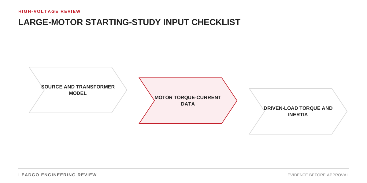
Large motors connect several disciplines: the utility or generator source, transformers and cables, motor electromagnetic design, starting equipment, protection, coupling and driven machine. This checklist gives buyers and engineers a shared basis for freezing those interfaces before approving direct-on-line, reduced-voltage, soft-starter or VFD starting.
Applicability and study boundary
Use this review where starting current or acceleration time can materially affect bus voltage, connected equipment, protection coordination or process restart. Typical triggers include high-voltage motors, large low-voltage motors, weak utility connections, generator-fed systems, long feeders, high-inertia equipment and sequential plant restart.
This method does not set a universal voltage-dip limit or permissible starting time. Those limits depend on the site network, connected loads, motor design, process tolerance and approved project documents. It also does not replace a transient-stability, harmonic or insulation-coordination study when one is required. State the boundary: source buses, generators, transformers, cables, starter, motor, transmission and driven load.
Starting-study input and ownership matrix
Build a register that identifies the source, revision, owner and status of every material input. Estimates may support early comparison, but must not appear as supplier guarantees.
| Input group | Controlled data required | Responsible source | Review question |
|---|---|---|---|
| Source | Operating voltage, impedance or fault level, generation dispatch and contingency | Power-system owner | Is this the weakest credible source, not only normal operation? |
| Transformers | Rating, impedance, vector group, tap and pre-start loading | Project electrical data | Are tap and parallel-unit assumptions stated? |
| Cables/reactors | Length, size, material and impedance | Approved schedule or supplier | Does the model match the selected route and conductor? |
| Existing loads | Running kW/kvar and voltage sensitivity | Site load list | Can important contactors, drives or controls drop out? |
| Motor electrical | Rated data and current-versus-speed curve | Offered motor supplier | Is the curve for the offered winding and voltage? |
| Motor mechanical | Torque-versus-speed curve, rotor inertia and start limits | Offered motor supplier | Is torque stated at modeled terminal voltage? |
| Driven load | Torque-versus-speed, inertia and initial condition | Driven-equipment supplier | Does it cover maximum credible process resistance? |
| Transmission | Gear ratio, efficiency and referred inertia | Package supplier | Are torque and inertia referred to one shaft speed? |
| Starting device | Topology, tap/current limit, ramp and transition logic | Starter or VFD supplier | Are transitions and bypass states represented? |
| Protection | CT data, relay curves, settings and logic | Protection engineer | Is acceleration clear of protection with agreed margin? |
| Scenarios | Normal, weak-source, restart and sequence cases | Operations/project team | Is each combination physically credible? |
| Acceptance | Voltage, acceleration, thermal and process limits | Approved specification | Is every limit traceable to a controlled requirement? |
Build the mechanical case first
Acceleration depends on the difference between motor torque and load torque. A current-only model cannot prove that the shaft will pass through a low-margin speed range. Obtain the offered motor torque-speed curve, load torque-speed curve, motor rotor inertia, driven-equipment inertia and transmission ratio. State whether inertia is referred to motor speed.
The load supplier should define breakaway conditions and the most demanding credible process state. A pump with a closed or open valve, a loaded conveyor and an unloaded compressor may present different starting duties. Do not select the convenient curve without an operating basis.
Model credible network scenarios
At minimum compare the approved normal case with the credible weak-source case. Consider generator dispatch, transformer taps, parallel equipment, pre-start loading, long cable runs and the restart sequence. Do not combine unrelated extremes into an impossible “worst case”; explain why each combination can occur.
Retain time traces for motor terminal voltage, affected bus voltages, source current, motor current, speed, motor torque and load torque. A final-speed result hides marginal acceleration zones. If control power, contactors or nearby drives have undervoltage behavior, include their tolerance or create a separate interface action.
Compare starting methods on one basis
Direct-on-line, reactor, autotransformer, soft-starter and VFD options must use the same network and mechanical assumptions. A soft starter lowers applied voltage and therefore motor torque; a lower source-current plot alone does not prove acceleration. Transition starters require review of current and torque during transition. A VFD review should include drive sizing, low-speed torque, cooling, harmonics and any bypass duty.
Record settings and tolerances rather than one nominal curve. Current limit, tap selection, ramp time and transition speed can change both voltage dip and acceleration. The selected device must satisfy electrical and process criteria in the same run.
Common errors that invalidate the result
- Using a catalogue-family motor curve instead of the offered rotor design.
- Treating rated current as starting current or locked-rotor values as constant to full speed.
- Omitting transformer, generator or feeder loading before the start.
- Combining motor data from one revision with load data from another.
- Referring gearbox-side inertia to the motor shaft incorrectly.
- Checking bus voltage without checking torque margin, start time and protection.
- Modeling only normal operation when the plant requires contingency restart.
- Hiding estimated inputs in a table of confirmed values.
- Rounding a marginal result without sensitivity checks.
- Closing the study before cable route, starter settings or motor design are frozen.
Decision steps and sensitivity checks
- Freeze equipment identities, model boundary and document revisions.
- Assign an owner to each input and separate confirmed data from estimates.
- Reconcile units, shaft-speed reference, voltage basis and per-unit bases.
- Run a normal case and check whether current and torque behavior are plausible.
- Run each credible weak-source and demanding-load case.
- Review voltage exposure of the motor and other connected equipment.
- Check positive acceleration margin and total time.
- Overlay protection operation and the motor supplier’s permissible-start basis.
- Vary uncertain high-impact inputs such as source impedance, inertia and load torque.
- Approve a starting method only when electrical, mechanical and process criteria agree.
Sensitivity testing matters when an input is provisional. Show whether a reasonable change reverses the decision. A result that passes only with an optimistic estimate remains an open engineering risk.
Supplier starting-study data return schedule
Request machine-specific current-speed and torque-speed curves, rotor inertia, permissible-start information, thermal or stall constraints relevant to the duty, and identification of the exact offered motor design. Ask the driven-equipment supplier for torque versus speed, inertia, breakaway torque, maximum starting condition, gearbox information and minimum acceleration requirements.
From the starter or VFD supplier, request topology, ratings, current-limit range, ramp or tap assumptions, transition sequence, bypass logic and modeled losses. Each file should carry an equipment reference, revision and date.
Conditions for freezing the starting method
The study is ready for closure when all high-impact inputs are approved or conservatively dispositioned; normal and credible abnormal cases meet traceable limits; acceleration clears protection and thermal constraints; connected-load voltage exposure is accepted; sensitivities do not overturn the decision; and the selected starter settings match procurement documents.
Keep the input register, model files, plots, assumptions, review comments and final settings together. Define which changes trigger rerun: source impedance, transformer or cable selection, motor curves, starter settings, load torque or inertia, protection or operating sequence. This turns the report from a one-time plot into a controlled design record.