
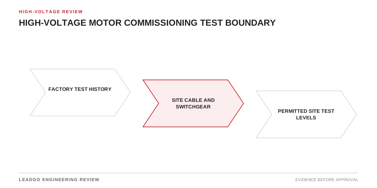
High-voltage motor commissioning is not a competition to perform the greatest number of tests. The useful program closes the risks introduced after factory acceptance: transport, storage, foundation work, cable termination, auxiliary installation, protection configuration, coupling and first energization. An unnecessary or poorly controlled electrical test can add insulation stress without answering a clear acceptance question.
The test boundary must therefore be agreed before site work begins. For each proposed test, record the risk addressed, equipment included, approved method, supplier restriction, pass criterion and owner. This makes omissions visible and prevents the motor, cable and switchgear boundaries from being confused.
Applicability and limits of this guide
Use this method for new or overhauled high-voltage induction or synchronous motors during site installation and first operation. It is also useful when a stored motor is released to service or when motor, cable, switchgear and driven equipment are supplied under different contracts.
This article does not prescribe universal insulation-resistance values, withstand voltages, vibration limits or protection settings. Test limits depend on machine rating, insulation system, temperature, test history, governing standards and approved supplier documentation. Specialized diagnostic methods require competent personnel and method-specific interpretation. Local electrical safety rules and the approved isolation procedure always control field execution.
Commissioning test-boundary matrix
| Review stage | Check or evidence | Primary risk addressed | Closure basis |
|---|---|---|---|
| Factory record | Routine/type/special test reports applicable to the serial-numbered motor | Unknown manufacturing acceptance | Reports match purchase specification and equipment identity |
| Receipt | Packaging, shock/tilt evidence, visible damage and completeness | Transport damage or missing parts | Exceptions photographed and dispositioned |
| Storage release | Heater records, preservation, cleanliness and condensation inspection | Moisture, contamination or corrosion | Storage deviations reviewed before testing |
| Mechanical installation | Foundation, soft foot, fasteners, alignment and shaft condition | Distortion, vibration and bearing load | Approved installation tolerances are recorded |
| Lubrication/cooling | Lubricant, oil system, cooling-water/air path and fan direction | Bearing or thermal damage | Auxiliary system functional checks pass |
| Motor offline electrical | Winding identity, resistance and approved insulation checks | Connection error, moisture or damage | Temperature-corrected or method-defined results accepted |
| Cable boundary | Cable and termination test records, phase identification and earth connection | Cable fault or wrong phasing | Cable owner releases the circuit |
| Auxiliaries | RTDs, heaters, bearing sensors, space heater and terminal circuits | Lost monitoring or incorrect control | Point-to-point and functional records complete |
| Protection | CT polarity/ratio, relay settings, trip circuit and interlocks | Failure to clear abnormal operation | Approved study and injection/functional tests agree |
| Uncoupled trial | Rotation, current balance, noise and basic vibration where permitted | Wrong rotation or assembly issue | Predetermined stop criteria remain clear |
| Coupled trial | Process load, vibration, bearing temperature and current | Alignment, load or cooling problem | Stabilized readings meet approved criteria |
| Baseline | Repeatable electrical, vibration and thermal readings | No reference for future condition monitoring | Method, load and sensor positions are retained |
The matrix distinguishes evidence from repeated testing. A valid factory record can close a manufacturing question, while site checks address conditions that changed after shipment.
Start with records and equipment identity
Confirm nameplate, serial number, terminal marking, drawings and accessories before connecting test equipment. Review the purchase specification, approved data sheet, factory reports, deviation register, transport records, storage log and supplier instructions. Missing records are not automatically solved by applying a more severe site test.
Create a single-line boundary drawing showing the motor, neutral arrangement where applicable, surge devices, cable, switchgear, grounding, current transformers and voltage transformers. Mark which components remain connected during each test. This avoids results being attributed to the motor when the test actually includes cable or accessories.
Control insulation testing rather than repeating stress
Insulation resistance can support a moisture or contamination review, but its interpretation depends on winding temperature, test voltage, test duration, connection and prior history. Record those conditions. Trend-compatible results are more useful than an isolated number without method context.
Any additional high-voltage withstand, very-low-frequency, dissipation-factor, partial-discharge or surge-related test needs a specific technical basis. Confirm compatibility with the motor insulation system, factory history, connected accessories and supplier instructions. Define whether the test is acceptance, diagnostic investigation or baseline measurement. Do not combine methods casually or infer universal limits from another machine.
If the cable requires a separate test, isolate it according to the approved procedure and protect motor-side equipment from inappropriate exposure. Reconnect only after discharge, grounding, inspection and phase confirmation.
Mechanical and auxiliary checks before energization
Verify foundation condition, hold-down fasteners, soft foot, alignment, coupling arrangement, shaft endplay where relevant, guards and driven-equipment readiness. Confirm the correct lubricant, quantity and supply path. For sleeve-bearing or forced-lubrication systems, prove oil flow and permissives before rotation.
Check cooling-air or cooling-water paths, filters, dampers, fans and heat-exchanger connections. Test winding and bearing temperature devices at the monitoring system, not merely at the terminal box. Confirm space-heater isolation logic so heaters cannot remain energized in a prohibited state.
Point-to-point checks should cover resistance-temperature detectors, vibration sensors, bearing alarms, leak detectors, differential protection leads, neutral equipment and local emergency stops as applicable. Use the final cable schedule and record discrepancies.
Protection and interlock verification
Commission protection against the approved study and motor data. Verify CT ratios, polarity, secondary grounding, relay inputs, setting groups, breaker trip circuit and lockout behavior. Map each trip and alarm to a functional test or justified secondary-injection result.
Starting time, locked-rotor protection and thermal modeling must agree with the actual starting method and load. If the final motor curve or start study changed, reconcile settings before energization. Confirm permissives for lubrication, cooling, driven equipment and process valves where required.
Energized trial sequence and stop criteria
Use a signed readiness review before the first start. Identify who may start and stop, the observation positions, communications method and immediate-stop criteria. Typical monitored quantities include voltage, phase current, acceleration time, rotation, vibration, bearing temperature, winding temperature, oil pressure or flow and abnormal noise.
An uncoupled run is not automatically appropriate for every motor or bearing arrangement. Obtain the applicable supplier and package instructions. If performed, it can confirm rotation and basic mechanical condition, but it does not prove coupled alignment or process duty.
For the coupled trial, start with an agreed process condition and increase load according to the commissioning plan. Record readings at defined times and stable operating points. Compare phase currents, bearing behavior and vibration by location. Do not average away one abnormal bearing or phase.
Common errors and false assurance
- Repeating factory tests without identifying the site risk being closed.
- Testing motor and cable together while interpreting the result as motor-only.
- Comparing insulation readings taken at different temperatures or durations without correction.
- Using a generic limit instead of the approved machine-specific basis.
- Energizing before lubrication, cooling and protection permissives are proven.
- Checking sensor resistance but not the full alarm and trip path.
- Accepting correct rotation before confirming the driven-equipment requirement.
- Running uncoupled without reviewing bearing or cooling restrictions.
- Recording vibration without sensor location, direction, speed and load.
- Closing commissioning while deviations, temporary settings or disconnected trips remain.
Decision steps for approving the boundary
- Identify the serial-numbered motor and all connected equipment.
- Review factory, transport and storage evidence for unresolved risk.
- Mark the isolation boundary for every proposed electrical test.
- State the purpose and acceptance basis of each test.
- Obtain supplier review for additional electrical stress or unusual methods.
- Complete mechanical, lubrication, cooling and auxiliary verification.
- Prove protection, interlocks, trip circuits and final settings.
- Conduct the first start under a controlled plan with stop criteria.
- Complete coupled-load checks at defined operating points.
- Resolve exceptions and retain repeatable baseline records.
Data to request from the motor supplier
Request serial-number-linked factory test reports, approved drawings and data sheet, terminal and connection information, winding and bearing temperature-device details, bearing and lubrication instructions, cooling requirements, permissible starts, starting curves, applicable installation tolerances and recommended commissioning procedure.
Where an additional insulation or diagnostic test is proposed, request written confirmation of method compatibility, connection, test voltage or stress basis, duration, temperature treatment and interpretation criteria. Also obtain restrictions for uncoupled running, jacking oil, pre-lubrication, shaft grounding, space heaters and transport locks as applicable.
Acceptance and closeout conditions
Commissioning can close when equipment identity and final drawings agree; factory, transport and storage exceptions are dispositioned; mechanical and auxiliary checks are complete; electrical tests use approved boundaries and criteria; cable and switchgear owners release their equipment; protection and interlocks pass; first-start and loaded-trial results meet approved limits; and all temporary connections or settings are removed.
The turnover package should include signed check sheets, calibrated-instrument identification, raw readings, temperature and load conditions, relay files, trip-test records, deviations, photographs where useful and baseline data. Open actions need named owners and operating restrictions. A clean summary without the underlying evidence is not a defensible release record.