
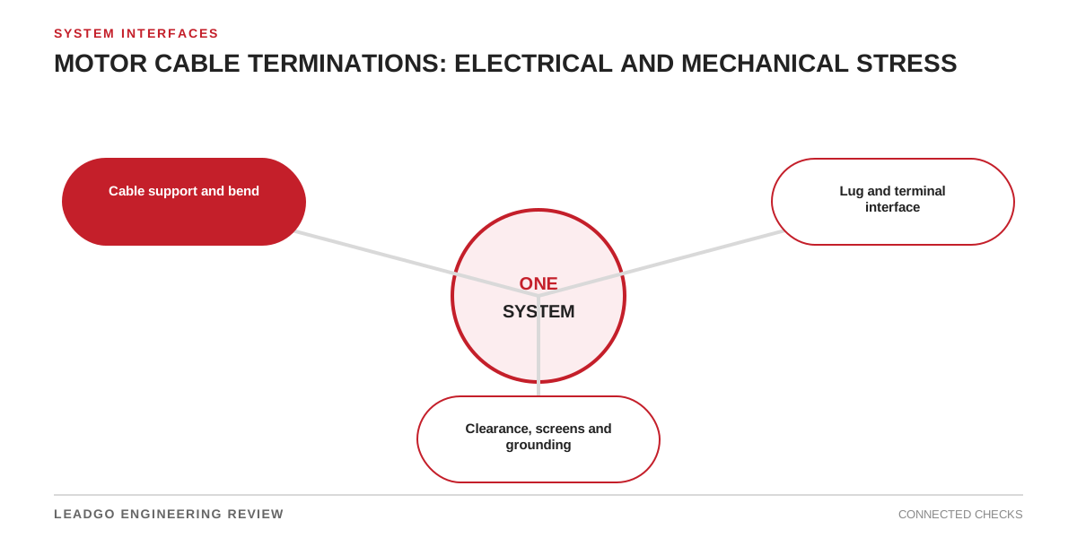
Motor cable design is not finished when ampacity and voltage drop are acceptable. The termination must fit the available box, preserve clearances and sealing, and keep cable forces away from insulated terminals.
Check the interface before pulling cable
| Interface | Required evidence | Failure to prevent |
|---|---|---|
| Conductor and lug | Size, material and approved lug range | Poor contact or incompatible hardware |
| Terminal stud | Diameter, stack arrangement and torque instruction | Stud bending or loose joint |
| Cable route | Entry point, bend radius and pulling direction | Side load on bushings |
| Support | Cleats/support distance and short-circuit restraint design | Cable weight transferred to terminals |
| Gland/seal | Cable diameter and enclosure requirement | Lost ingress protection |
| Earth/screen | Grounding drawing and VFD/EMC design | Unsafe or ineffective return path |
A general arrangement drawing should show the cable approach, not only the terminal-box outline.
Remove mechanical preload
Support and form the cable before final lug tightening. A lug that must be forced into position will continue loading the stud after the cover is fitted. Check that phase links, stress-control components and sensor wiring remain clear.
For large or stiff cables, coordinate the terminal-box orientation and entry side during procurement. Field rotation may change drain, sealing or certified details.
Make the final inspection reproducible
Record lug identity, tightening method, cable support, gland components and photographs before closing the box. Inspect for strand damage, foreign material and inadequate phase separation.
Related reading: terminal-box position and cable entry and motor grounding and earthing.