
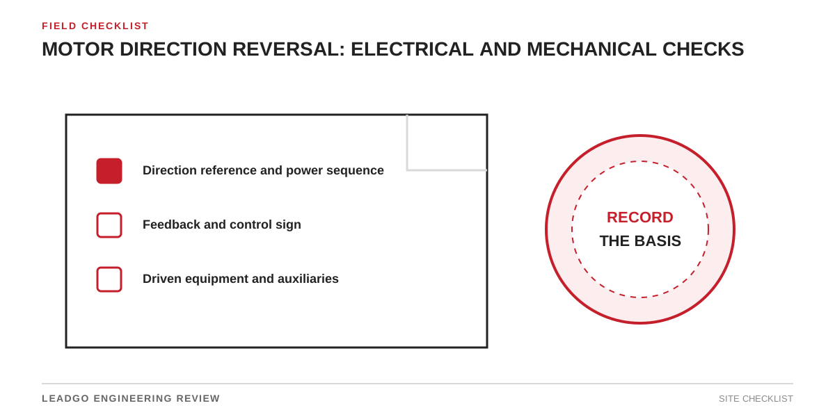
Changing rotation looks like a two-wire task only when the motor is considered alone. In an operating plant, direction is shared by the motor, coupling, driven equipment, auxiliaries, feedback and control logic. A correct terminal change can still produce a failed pump, a disengaged fan, a backstop conflict or positive feedback.
Establish the direction reference first
Write down the viewing position. “Clockwise” is ambiguous unless the drawing states whether the observer faces the drive end or non-drive end. Use the approved general-arrangement drawing, the rotation arrow on the machine and the driven-equipment manual as the common reference.
Photograph the original terminal arrangement and record phase identification before moving conductors. Confirm that the motor is isolated and that stored mechanical or electrical energy has been released under the site procedure.
Choose the correct reversal method
| Supply and machine | Electrical action | Additional check before running |
|---|---|---|
| Line-fed induction motor | Interchange any two incoming phases | Starter interlocks, phase identification and driven-equipment direction |
| VFD-fed induction motor | Change the drive direction command or approved motor-phase arrangement | Drive permissives, minimum speed, ramp and reverse inhibit |
| Encoder-controlled motor | Follow the drive maker’s direction procedure | Encoder channel order, speed sign and closed-loop stability |
| PM or synchronous system | Use the commissioned drive configuration | Rotor position, feedback offset and motor identification data |
Do not improvise by changing both the phase order and the software direction at the same time. That can make the shaft turn as expected while leaving the internal sign convention wrong.
Check the machine beyond the coupling
A centrifugal pump may develop little or no head in reverse. A fan may still move air, but at the wrong volume and efficiency. A conveyor backstop or screw conveyor can be mechanically direction-sensitive. Some reciprocating machines depend on a defined crank position and unloading sequence.
Review these interfaces before the bump test:
- coupling and guard readiness;
- lubrication or jacking-oil system operation;
- separately powered cooling fan direction;
- backstop, brake and ratchet orientation;
- pump suction condition or compressor unloading;
- process valves, dampers and downstream permissives.
Feedback can turn reversal into positive feedback
When speed or position feedback is used, the controller’s commanded direction and measured direction must share the same sign. A mismatch can cause immediate current limit, overspeed demand or unstable torque. Keep the first closed-loop run at the approved low-risk condition and verify actual speed against the drive display.
Current transformers and directional protection also deserve attention on systems where power-flow direction or differential polarity matters. Reversing motor leads is not permission to reverse protection wiring without a reviewed scheme.
Release criteria after the bump test
- The shaft turns in the direction shown on the approved drawing.
- The driven equipment and every direction-sensitive auxiliary agree.
- Encoder speed and direction match an independent observation.
- No reverse-rotation alarm, backstop contact or abnormal sound appears.
- Terminal changes, software changes and test results are recorded together.
If any item is uncertain, keep the coupling or process release on hold. The useful record is not “rotation checked”; it is the viewing reference, phase arrangement, observed direction and the person who accepted the driven-equipment result.
What to send with a replacement-motor enquiry
Include the existing nameplate, terminal diagram, viewing direction, coupling arrangement, driven-equipment rotation arrow and whether a VFD or encoder is fitted. LEADGO can then check terminal marking and motor suitability against the actual system rather than infer direction from a motor photograph.