
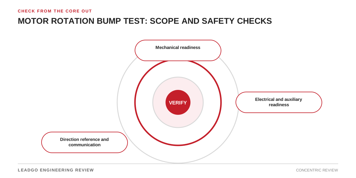
Wrong rotation can damage pumps, fans, compressors and process equipment. The direction check itself can also create unexpected shaft movement, pressure or material flow. It should be led by authorised personnel under the site’s isolation, energisation and commissioning rules.
Go/no-go review before the command
| Boundary | Evidence required before the test | Stop condition |
|---|---|---|
| Driven equipment | Approved coupled or uncoupled configuration; free-movement check where applicable | Unknown mechanical state, shipping restraint or blocked machine |
| Coupling and shaft | Keys, coupling parts and guards controlled for the stated test setup | Loose key, unsupported coupling component or exposed hazard |
| Process | Valves, dampers, pressure, material and downstream consequences reviewed | Motion can create an uncontrolled process condition |
| Motor auxiliaries | Lubrication, cooling, brakes, space heaters and sensors in the correct test state | Required auxiliary unavailable or brake status uncertain |
| Electrical system | Grounding, protection, command source and isolation boundaries verified | Unclear control authority or incomplete protection |
| Direction reference | Arrow, viewing end and required driven-equipment rotation marked | Team members are using different viewing references |
The test leader should confirm who may issue the command and who may stop it. Radio or hand-signal ambiguity is a reason to pause.
Use the minimum authorised movement
The commissioning procedure should define the command method and permitted movement. Do not improvise pulse duration or bypass interlocks to obtain a clearer view. If direction cannot be observed safely, use an approved alternative such as phase-sequence verification combined with a documented equipment check.
For VFD-fed motors, confirm local/remote control, speed reference and drive logic before the test. A stored command, automatic restart feature or process permissive can defeat the assumption that only a brief manual command will occur.
Close the record before normal operation
- Identify the motor, driven equipment and viewing end.
- Record observed rotation and the roles completing the check.
- If conductors are changed, repeat the controlled verification and update the termination record.
- Restore guards, coupling arrangements, interlocks and normal control mode under the approved procedure.
Direction changes can affect more than two power leads when encoders, brakes or process logic are involved. Use motor direction reversal checks for the wider interface review.