
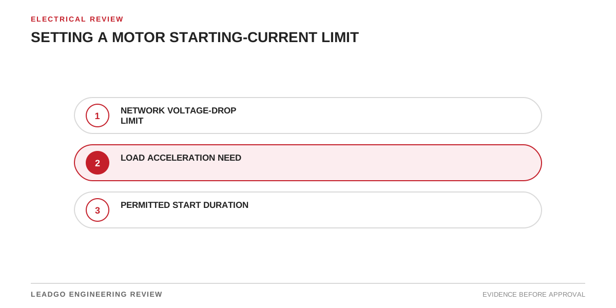
“Starting current shall not exceed 300%” looks precise, but it may be impossible to price or verify. Three hundred percent of which current? Measured at the motor, starter input or utility point? Is it a symmetrical RMS value, a transient peak, a maximum meter reading or a simulated envelope? Must the motor start a loaded machine at minimum voltage? Without those definitions, bidders can comply with different interpretations.
A useful limit starts with the system problem—voltage dip, generator capacity, tariff demand, equipment rating or process disturbance—and converts it into a testable interface requirement. It must also preserve enough motor torque to accelerate the load.
Applicability and specification boundary
Use this method when a project constrains motor inrush or starting demand for direct-on-line, reactor, autotransformer, star-delta, soft-starter or VFD starting. It is especially relevant on weak utility networks, generator or island systems, long feeders, buses with sensitive loads and projects where several motors restart in sequence.
The method does not establish one universally safe multiple of rated current. Suitable values depend on source impedance, motor design, load torque, inertia, starter topology and process requirements. The approved starting study, equipment standards and contractual documents control the final value.
Starting-current requirement decomposition
| Requirement field | Question to answer | Evidence owner | Contract output |
|---|---|---|---|
| Purpose | What system risk is the limit controlling? | Project electrical engineer | Stated design objective |
| Reference current | Rated motor current, starter input current or point-of-connection current? | Buyer/system engineer | Defined denominator |
| Measurement point | At motor terminals, starter input, feeder or bus? | One-line owner | Marked location |
| Quantity | RMS symmetrical, peak, fundamental or demand value? | Study/test authority | Defined calculation method |
| Time treatment | Instantaneous maximum, cycle window or time-current envelope? | Study/test authority | Sampling and reporting rule |
| Supply case | Nominal or minimum voltage, source impedance and topology? | Network owner | Credible operating scenarios |
| Motor tolerance | Which offered motor curve and manufacturing tolerance? | Motor supplier | Guaranteed or controlled curve |
| Starter behavior | Current-limit range, transition and tolerance? | Starter supplier | Setting and performance envelope |
| Load duty | Torque-speed curve, inertia and initial process state? | Package supplier | Maximum credible start case |
| Acceleration | Required maximum time and minimum torque margin? | Process/package engineer | Acceptance criterion |
| Thermal duty | Cold/hot starts, starts per hour and stall exposure? | Motor supplier | Permissible-start basis |
| Verification | Simulation, factory test or site measurement? | Contract owner | Acceptance procedure |
This table prevents a headline percentage from becoming the only specification. Every row affects whether two supplier offers are technically comparable.
Understand the current–torque trade-off
For conventional reduced-voltage starting, reducing applied voltage lowers current, but it also reduces motor torque substantially. The exact relationship depends on the motor and starter, so use machine-specific curves rather than a slogan. A current limit that looks attractive to the network engineer can leave little accelerating torque at a critical speed.
Acceleration time then increases, exposing the motor to high current for longer. The project must compare source-current reduction with motor heating, starter duty, process time and protection settings. A soft starter can regulate current during the ramp, but it cannot create torque that the reduced terminal voltage does not support. An autotransformer or reactor changes the relationship between source current and motor terminal conditions, so identify which side the limit applies to.
A VFD provides a different control mechanism. It can vary frequency and voltage to develop torque at reduced source current, subject to drive rating, control mode, low-speed cooling and load requirements. Do not apply a direct-on-line current multiple to a VFD input without defining harmonics, power factor, overload and acceleration assumptions.
Convert network need into a motor-start envelope
Begin with the allowed bus-voltage effect and credible network cases. Model source impedance, transformers, generators, feeders, existing loads and sensitive contactors or controls. The resulting allowable current may be a time-dependent envelope rather than one number.
Next, model the offered motor and actual driven load. Use current-speed and torque-speed curves, combined inertia and the most demanding credible start condition. Check terminal voltage throughout acceleration. Confirm that the motor passes every speed point with positive accelerating torque and reaches operating speed within the permitted thermal boundary.
If no design satisfies both the network and acceleration requirements, the project must change a real constraint: strengthen the source, modify the feeder, unload the process, extend an approved acceleration time, choose another starter, add a VFD or revise the motor/load package. Rewording the current limit does not resolve the physics.
Common current-limit specification errors
- Stating a percentage without defining the reference current.
- Confusing initial peak current with RMS symmetrical current.
- Measuring starter input current while specifying motor-terminal current.
- Applying the limit only at nominal voltage and strong-source conditions.
- Assuming lower current automatically means lower motor heating.
- Ignoring transition current in star-delta or autotransformer starting.
- Using a generic torque curve from a motor family.
- Omitting load inertia or using an unloaded process curve.
- Specifying current without a maximum acceleration time.
- Forgetting starter tolerance and current-transformer accuracy.
- Treating a simulated value as a guaranteed field measurement.
- Setting protection before final start time and current are known.
Decision steps for selecting the limit
- Record the business or system reason for constraining starting current.
- Define the electrical measurement point and reference current.
- Define RMS, peak, fundamental and time-window terminology.
- Freeze normal and weakest credible source configurations.
- Obtain motor current-speed and torque-speed curves.
- Obtain load torque-speed, inertia and initial process state.
- Compare feasible starting methods on the same network and load basis.
- Calculate acceleration, bus voltage, thermal exposure and protection clearance.
- Apply supplier tolerances and sensitivity cases.
- Select a limit that all credible cases can meet.
- Define how the requirement will be demonstrated and measured.
- Transfer final settings and restrictions into commissioning documents.
Document the rejected options as well as the selected value. That record helps later teams understand whether the limit is controlled by a utility connection, generator, motor torque, process requirement or commercial choice.
Supplier and RFQ return requirements
The motor supplier should return rated current, locked-rotor current, current-speed and torque-speed curves, rotor inertia, permissible starts, thermal or stall information, tolerances and identification of the offered design. Request curves at the relevant supply condition where needed.
The starter or drive supplier should return topology, input and output current definitions, current-limit range and tolerance, ramp or transition sequence, bypass behavior, overload rating, expected losses and model data suitable for the study. The driven-equipment supplier should state torque versus speed, inertia, breakaway condition, maximum loaded-start case, unloading provisions and acceptable acceleration.
The RFQ must say whether compliance is based on reviewed calculations, factory testing, site measurement or a combination. Define instrument class, sampling, averaging, voltage condition and permitted test tolerance before bids are compared.
Acceptance, verification and change control
Close the requirement when the selected starting method meets the defined current envelope at the specified point; all credible source and load cases accelerate successfully; bus voltage, thermal duty and process time remain within approved limits; protection passes the start and covers stall; and supplier tolerances do not reverse the decision.
During commissioning, record the actual source condition, initial process state, voltage, current and acceleration time. A field result taken under a light load or strong network does not prove the worst contractual case unless that equivalence is demonstrated.
Retain the study, curve revisions, settings and test record. Reopen the assessment when motor design, transformer tap, generator configuration, cable, starter setting, driven load, process start condition or operating sequence changes.