
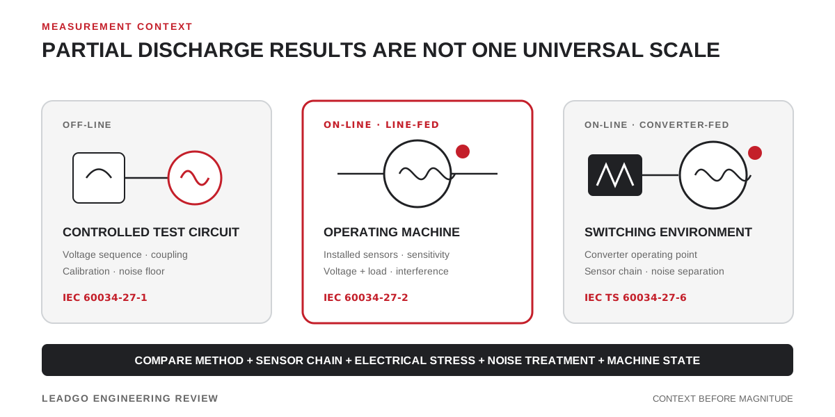
A partial-discharge number without its measurement context is not a motor condition rating. Sensor position, coupling network, bandwidth, electrical stress, background interference and winding construction all influence the recorded signal. A useful comparison therefore starts with the test method, not the largest value on the screen.
Choose the measurement context first
The IEC 60034 series separates several PD situations because they do not create interchangeable evidence.
| Motor and test state | Relevant IEC reference | What must be fixed before comparison |
|---|---|---|
| Off-line winding test | IEC 60034-27-1:2017 | Test circuit, applied voltage sequence, coupling device, calibration, noise floor and winding connection |
| On-line, non-converter-driven machine rated 3 kV and above | IEC 60034-27-2:2023 | Installed sensor arrangement, sensitivity assessment, operating voltage and load, instrument setup and interference treatment |
| On-line, converter-supplied winding | IEC TS 60034-27-6:2026 | Converter topology and operating point, sensor chain, switching-related interference and the procedure selected for converter-fed service |
The purpose must also be clear. A factory test, commissioning baseline and long-term trend can all be valid, but they should not share an unnamed acceptance threshold.
Preserve the evidence behind the magnitude
Apparent-charge magnitude is only one part of an electrical PD record. Keep the phase-resolved pattern, repetition behaviour and channel information so that internal activity can be distinguished from switching noise, arcing, sparking or external interference. Document any gating, filtering or noise-rejection step; otherwise a later reviewer cannot know what the instrument removed.
IEC 60034-27-2:2023 includes measuring techniques, installation arrangement, sensitivity assessment, noise reduction, documentation and interpretation in its scope. That list is a useful reminder that the displayed magnitude is the end of a measurement chain, not a property that can be detached from it.
Build a comparison envelope
For each trace or trend point, retain:
- motor serial number, winding connection and sensor channel;
- on-line or off-line state and the governing procedure;
- line-fed or converter-fed supply and the relevant operating point;
- voltage, current or load, winding temperature and ambient condition;
- coupling device, sensor location, instrument, bandwidth and settings;
- calibration or sensitivity assessment and the recorded noise floor;
- unfiltered and processed data where the system permits both;
- pattern interpretation, reviewer, date and any unresolved interference.
Trend alarms should be based on comparable records from the same measurement system and operating envelope. If hardware or software changes, create a documented bridge measurement rather than joining the old and new data silently.
Avoid false rankings
Two machines with different winding designs can produce different PD behaviour without one being in worse condition. The same motor may also look different at another voltage, load, temperature or noise environment. A fleet chart that ignores these variables can push maintenance toward the wrong asset.
Use the result to answer a bounded question: Did a repeatable pattern change under comparable conditions? Does it correlate with another channel or inspection finding? Has a known noise source been excluded? The disposition should follow the selected standard, manufacturer guidance and asset-specific history.
Release decision
Do not accept or reject a high-voltage motor from one isolated PD magnitude. Approve the assessment when the method matches the supply and test state, the measurement chain is traceable, interference has been addressed and the conclusion is supported by comparable patterns or trend evidence. Where those conditions are not met, record the test as a baseline or an investigation lead rather than a final diagnosis.
Related reading: