
A PTC chain is suited to threshold action, while an RTD provides a resistance value that can be converted into temperature. Neither device protects anything until the input module, logic, trip circuit and reset policy are defined.
Choose the signal by its job
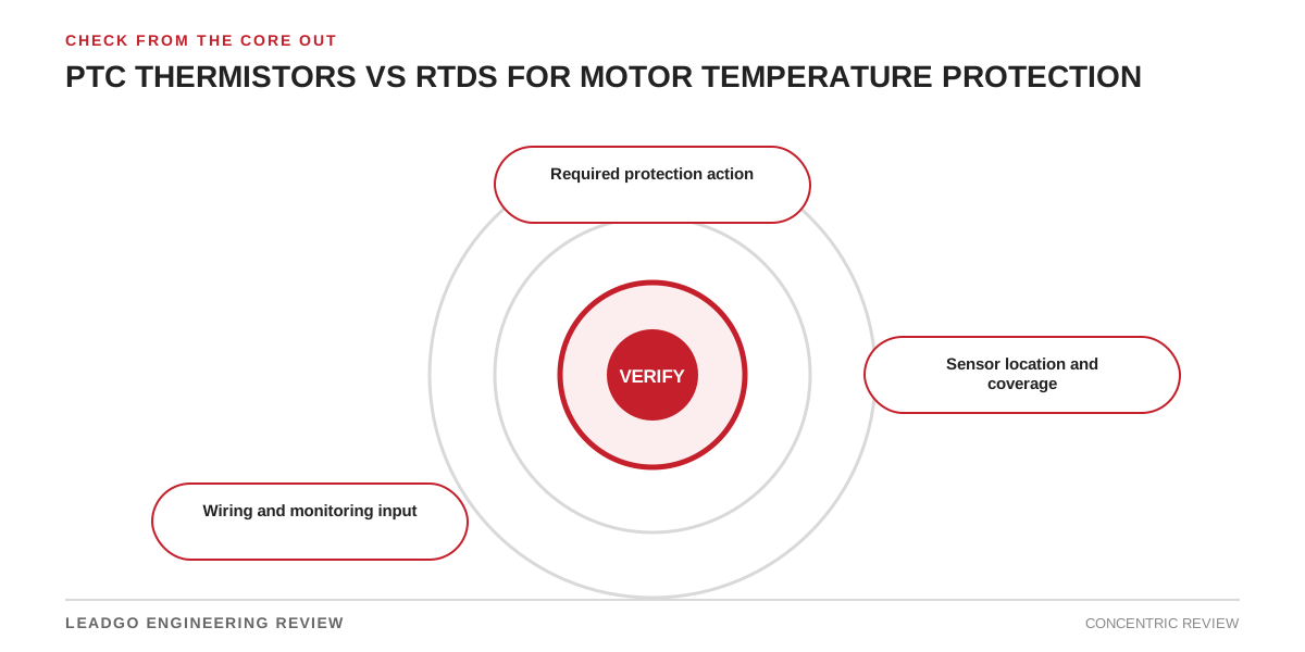
Trace every sensor to a winding or bearing position. Confirm detector count, lead arrangement, insulation, input type and galvanic separation. A PLC analogue card is not automatically an approved protection relay.
Sensor choice
| Item | Engineering purpose | Review action |
|---|---|---|
| PTC | Threshold response | Trip or alarm near a designed temperature |
| RTD | Continuous measurement | Display, alarm and trend |
| Three-wire RTD | Lead compensation | Longer field runs |
| Spare element | Service continuity | Documented terminal allocation |
Evidence required before approval
Simulate each channel at the terminal box and receiving device. Record alarm and trip operation, open-circuit response and tag correspondence. Approve only when location, input compatibility and final action are proven.
Retain the equipment revision and test record. Name the reviewer. Keep open assumptions visible.
Commissioning decision
Never approve a copied setting. Confirm interface compatibility and operating limits. Exercise the intended response during a functional test.