
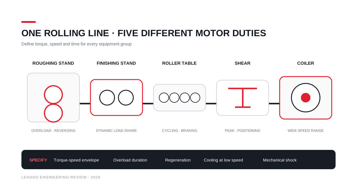
A rolling mill is not one motor application repeated down a production line. The main stand, roller table, shear, coiler, hydraulic unit and cooling auxiliaries each impose a different electrical and mechanical duty.
The practical way to specify the motors is to split the line into duty groups, then make the drive supplier and mechanical-equipment supplier agree on each torque-speed-time profile.
Map the line before choosing motors
| Equipment group | What usually drives selection |
|---|---|
| Roughing or reversing stand | High torque, short overload, acceleration and reversing sequence |
| Finishing stand | Dynamic speed control, coordinated load sharing and thermal cycling |
| Roller table | Frequent acceleration, braking and possible reversing |
| Shear | Short cyclic peaks, positioning and mechanical shock |
| Coiler or uncoiler | Wide speed range and changing torque as coil diameter changes |
| Pumps and fans | Continuous duty, process control and site environment |
This grouping stops a common mistake: copying the main-stand service factor onto every auxiliary while leaving the dynamic requirements undefined.
Use a torque-speed-time profile
Rated kilowatts describe one continuous point. A stand motor may spend much of its cycle accelerating, accepting the strip, carrying a short rolling peak and decelerating. A coiler sees its mechanical ratio change continuously as the coil builds.
For each machine, provide:
- base and maximum speed;
- continuous, short-time and peak torque;
- duration and repetition of each load segment;
- acceleration, deceleration and reversing times;
- load inertia referred to the motor shaft;
- allowable speed droop and control accuracy;
- normal and emergency stopping sequence.
The motor thermal model should be checked against the cycle, not a simple average power. A short overload can be acceptable only when its magnitude, duration, repetition and starting temperature are known.
Motor and converter must be selected together
Variable-speed operation changes cooling and insulation stress. At low speed, a shaft-mounted fan may provide less cooling while the motor is producing substantial torque. Separately powered ventilation or another cooling arrangement may be needed.
At high speed, field weakening changes the available torque. The motor-drive proposal should show the continuous and short-time torque envelope across the full speed range, including the site’s minimum and maximum supply conditions.
Reversing and deceleration can return energy to the DC bus. Define whether the system uses a regenerative front end, common DC bus, braking equipment or another arrangement. The grid, harmonics, power factor and protection review belongs to the complete drive system.
Use the checks in matching a VFD to a motor rather than treating the converter as a separate catalogue item.
Mechanical shock cannot be hidden in a service factor
Strip bite, cobbles and shear operation can create transient torque and shock. Provide coupling and gearbox data, shaft loads, backlash, torsional stiffness and credible upset conditions.
Assign responsibility for torsional analysis. The model may need the motor electromagnetic response, converter controls, coupling stiffness, gearbox train and driven inertia. A motor shaft sized only from rated torque does not settle that study.
For replacement work, survey shaft height, shaft extension, hold-down points, coupling position, cooler clearance and cable-entry orientation. A matching frame number does not prove interchangeability.
Heat, scale and water shape the enclosure
Steel plants combine radiant heat, conductive dust or scale, water spray, vibration and restricted access. Record the conditions at the motor location rather than using a plant-wide ambient value.
Define:
- maximum ambient and nearby radiant-heat sources;
- scale, dust, water and steam exposure;
- indoor or outdoor installation;
- cooling-air or cooling-water quality;
- cleaning practice and access;
- corrosion protection;
- altitude and ventilation-room conditions.
The cooling system needs monitoring and maintenance access. For water-cooled equipment, state inlet temperature, flow, pressure, water quality and alarm logic. For air-cooled equipment, define how coolers and external surfaces will be cleaned without stopping production unexpectedly.
Instrumentation must match the failure modes
Winding and bearing temperature, vibration, cooling status, encoder feedback and insulation monitoring may all be relevant. More sensors do not automatically create better protection.
Specify sensor locations, accuracy, wiring, alarm and trip levels, DCS ownership and commissioning tests. Record baseline vibration and temperature at representative loads. The guide to motor differential protection helps for applicable high-voltage machines, but the complete relay philosophy remains project-specific.
Build the enquiry in five schedules
- Duty schedule: torque, speed and time for every operating state.
- Electrical schedule: voltage, network data, converter, regeneration and protection.
- Mechanical schedule: shaft, coupling, gearbox, loads, inertia and torsional responsibility.
- Environment schedule: heat, scale, water, altitude, cooling and access.
- Verification schedule: design review, routine tests, witnessed tests and commissioning records.
LEADGO’s YKK/YXKK high-voltage induction motors and variable-frequency ranges can be considered where their documented rating and construction match a duty group. The line study—not the industry label—decides which machine belongs at each position.