
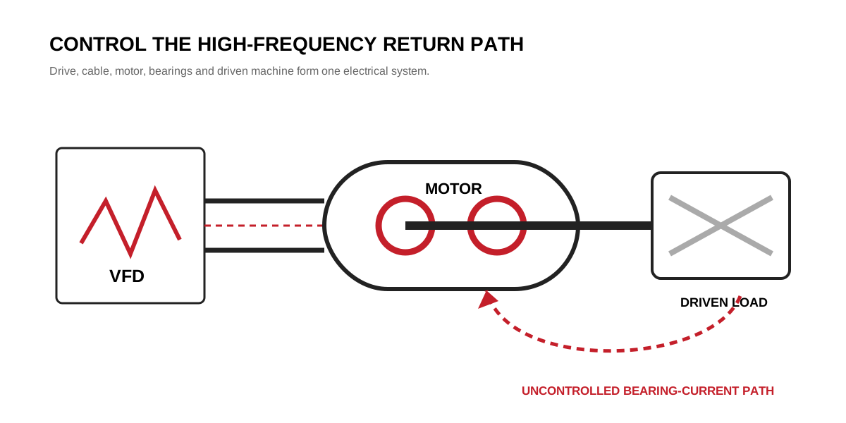
Variable-frequency drives switch voltage rapidly. The resulting common-mode voltage and high-frequency currents can find a return path through the motor shaft, bearings, frame and driven machine. When the voltage across a bearing film becomes high enough, a discharge can remove microscopic material from the raceway. Repetition produces frosting, pitting and eventually fluting.
ABB’s Technical Guide No. 5 describes three main high-frequency mechanisms: circulating currents, shaft-grounding currents and capacitive discharge currents. The mechanism depends on motor size, frame and shaft grounding, cable construction, bonding and drive characteristics. That is why a single accessory cannot be specified as a universal solution.
Recognise the current paths
| Mechanism | Simplified path | Typical design response |
|---|---|---|
| Circulating current | Shaft end → bearing → frame → opposite bearing | Break the loop, often with bearing insulation |
| Shaft-grounding current | Motor frame/shaft → driven machine → earth return | Improve high-frequency bonding and provide a controlled shaft path |
| Capacitive discharge | Winding/rotor capacitance → shaft → bearing | Reduce voltage stress and control the discharge path |
These descriptions are diagnostic categories, not purchasing rules. Insulating both motor bearings without reviewing the coupling and driven machine can move the discharge into a gearbox or load bearing.
Why ordinary grounding may not be enough
A protective earth conductor is essential for safety, but a conductor that works at mains frequency can have substantial impedance at the fast switching frequencies of a drive. Long pigtails, poor 360-degree shield termination and painted mounting faces can force high-frequency current onto unintended paths.
The installation should use the drive manufacturer’s recommended symmetrical motor cable, shield termination, bonding and grounding arrangement. Cable length and output filtering also affect stress. Our overview of common-mode and differential-mode EMC explains the distinction.
Warning signs in service
The first visible symptoms are often rising bearing noise and vibration. Raceways may show:
- dull grey frosting;
- small electrical pits;
- regularly spaced fluting;
- grease darkening or contamination from wear debris.
These signs are not enough on their own. Mechanical looseness, poor lubrication, misalignment and vibration can also damage bearings. Preserve the removed bearing, document both raceways and correlate the pattern with shaft-voltage and installation measurements.
Mitigation options
An engineered package may include:
- correct high-frequency bonding between drive, motor and driven equipment;
- properly terminated shielded motor cable;
- an insulated bearing at the specified end;
- a shaft-grounding brush or ring where an intentional path is appropriate;
- a common-mode choke, dV/dt filter or sine-wave filter when required by the drive system;
- insulated coupling or driven-equipment protection in special arrangements.
The selection depends on where current is generated and where it returns. For large motors, circulating current is often a central concern; smaller drive-fed systems can still experience capacitive discharge depending on installation conditions.
Commissioning checks
Review bearing-current risk before startup, not after the first bearing replacement. Record:
- drive make, topology and switching settings;
- motor frame, bearing arrangement and insulated-bearing location;
- cable type, length and shield termination;
- motor-frame and driven-machine bonding;
- coupling type;
- shaft-to-frame voltage where trained personnel and suitable equipment are available;
- baseline vibration and bearing noise.
Changing carrier frequency can affect losses, acoustic noise and voltage behaviour, but it should not be used as a blind cure. Confirm the drive and motor limits first.
Specify the system, not one component
A quotation should state whether insulated bearings, shaft grounding, special cable or an output filter are included and why. The motor supplier needs the drive type, cable length, grounding system and driven equipment—not only voltage and kW.
The same system approach applies when matching a VFD to a motor. Bearing-current protection succeeds when the intended high-frequency return path is lower impedance than the bearing path. Without that installation discipline, replacing the bearing treats the damage while leaving the electrical cause untouched.