
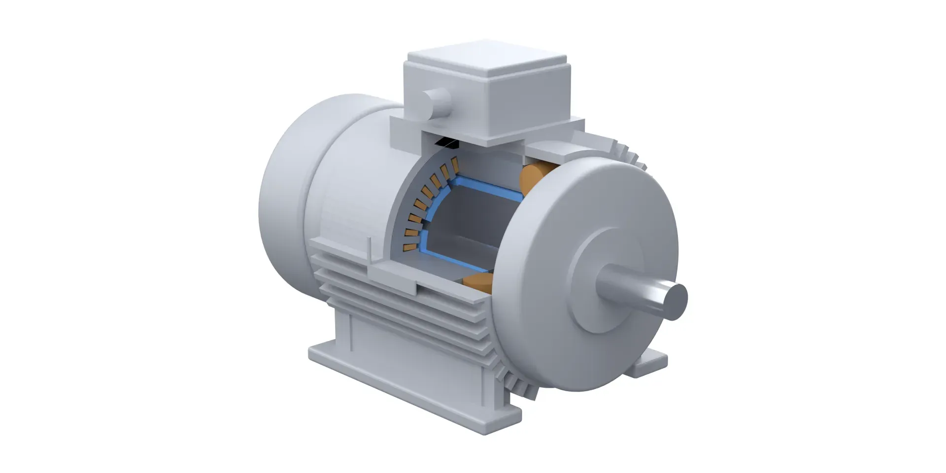
A permanent magnet synchronous motor, or PMSM, is a three-phase AC motor whose rotor carries permanent magnets instead of a winding or a cage. The stator creates a rotating magnetic field, the magnets lock onto it, and the rotor turns at exactly the speed of that field. There is no slip. A change in load changes how far the rotor trails the field. It does not change how fast the rotor turns.
This page covers how that works, how a PMSM gets started, what is inside one, and how it compares with an induction motor. The figures are schematics, not drawings of a specific LEADGO design.
The short answer
Three facts define a PMSM.
- The stator is an ordinary one. It is a laminated steel core with a three-phase winding. Gieras and Shen note that there is no essential difference between the stators of polyphase synchronous and induction machines of comparable rating.
- The rotor is made of steel and magnets. The magnets, usually rare earth, sit on the rotor surface or inside the core.
- Speed is fixed by frequency. Rotor speed in revolutions per second equals the supply frequency divided by the number of pole pairs. A 4-pole motor has two pole pairs, so at 50 Hz it turns at 25 rev/s, which is 1,500 rpm.
Everything else about a PMSM follows from one change: the rotor field comes from magnets, not from currents induced in the rotor.
How a PMSM works
Three-phase current in the stator winding produces a magnetic field that sweeps around the bore at a speed set by the supply frequency. In an induction motor that field induces currents in the rotor, and the rotor always runs slightly slower than the field. The gap between the two speeds is the slip.
A PMSM rotor already has its own north and south poles. The rotating stator field pulls them round, the way a rotating magnet drags a compass needle. Once the rotor is locked on, it turns at field speed whatever the load.
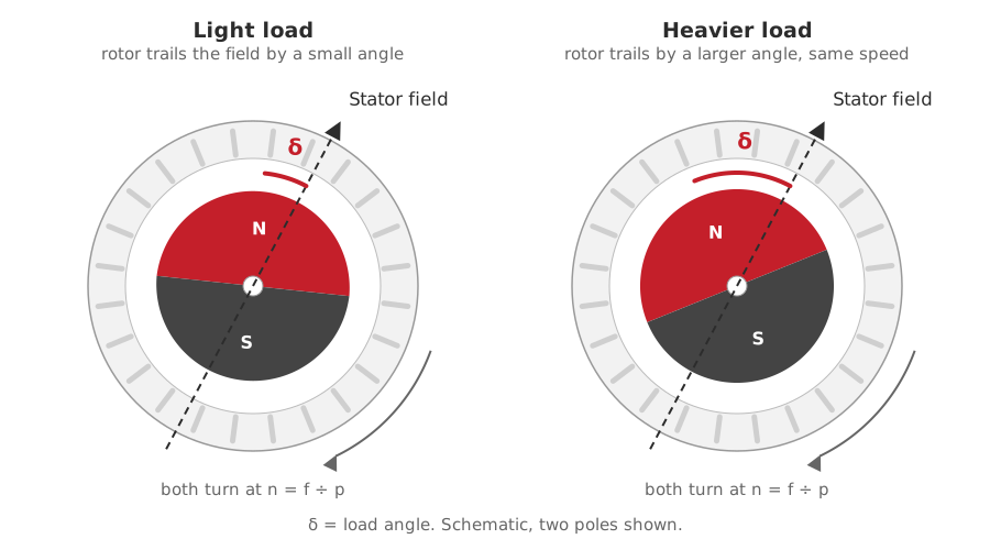
Figure 1. The rotor magnets follow the stator field. Load changes the trailing angle δ, not the speed.
When the load rises, the rotor slows for a moment. It then settles back at the original speed, but displaced further behind the field. That displacement is the load angle, and it supplies the extra torque. Hughes and Drury point out that you can see it with a stroboscope synchronised to the supply: a mark on the shaft drops back a few degrees each time the load increases.
The angle has a limit. Overload the motor far enough and the rotor can no longer keep up. It falls out of step with the field and stalls. That is why a PMSM needs torque margin above the worst load peak of the machine it drives.
Why a PMSM cannot start by itself
Gieras and Shen are direct about it: a synchronous motor is not self-starting. At standstill, the stator field sweeps past the rotor magnets far too fast for them to lock on. They are pulled forward and pushed back in turn, and the average torque is zero. Something else has to bring the rotor up to speed first.
Two ways to start and run one
There are two common answers, and they lead to two different kinds of motor.
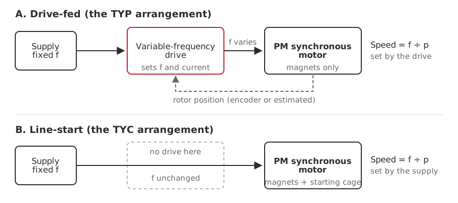
Figure 2. What changes between the two arrangements is the drive in the path and the cage in the rotor.
Drive-fed. A variable-frequency drive raises the frequency from a low value and the rotor follows. The drive needs to know where the rotor is, so it takes position from an encoder, or estimates it from the motor’s own electrical signals when there is no encoder. Speed is set by the drive across the whole range. This is the arrangement behind the TYP series.
Line-start. The rotor carries a cage winding as well as magnets. It starts as an induction motor straight from the supply, then pulls into step. Gieras and Shen report that such motors can run without a converter, that their efficiency is higher than that of an equivalent induction motor, and that the power factor can reach unity. They also name the costs. The magnets produce a braking torque during starting, which lowers the starting torque and the ability to pull a load into synchronism, and the air gap carries more space harmonics than an induction motor’s. This is the arrangement behind the TYC series.
A line-start motor runs at the speed set by the supply frequency. Whether a particular design can also run from a drive is a design question, so ask the manufacturer before assuming it can. For the starting behaviour in more detail, see how permanent magnet motors start and line-start PM motors without a drive.
What is inside
The stator, the shaft and the bearings look much like those of an induction motor. The rotor is where a PMSM differs: a laminated steel core carrying the magnets, with no winding.
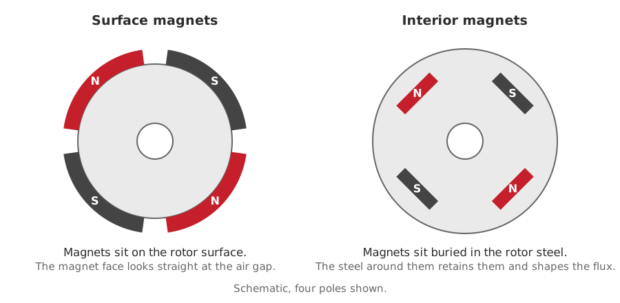
Figure 3. Surface magnets face the air gap directly. Interior magnets sit inside the steel, which retains them and shapes the flux.
The magnets can be mounted on the surface or buried in the core. The choice affects how the rotor handles speed, torque and field weakening, and interior versus surface permanent magnet rotors goes through it.
One risk belongs to magnet rotors alone. Unlike an induction motor, a PMSM can lose magnet strength if the rotor gets too hot or the opposing field from the stator gets too strong. The margin depends on the magnet grade, the rotor temperature and the operating point. There is no single threshold that fits every motor, which is why permanent magnet motor demagnetization is worth reading before you specify a high-ambient duty.
PMSM versus induction motor
| PM synchronous motor | Induction motor | |
|---|---|---|
| Speed under load | Constant, set by frequency | Falls slightly as load rises (slip) |
| Rotor losses | None in a magnet rotor | Rotor winding loss |
| Power factor | Can be adjusted through the drive, up to unity | Set mostly by the air gap, lower at light load |
| Torque against voltage | Roughly proportional to voltage | Proportional to voltage squared |
| Air gap | Larger, to limit armature reaction | As small as practical |
| Starting | Needs a drive or a starting cage | Self-starting |
| Purchase cost | Higher | Lower |
Based on Gieras and Shen, table 7.3 and section 7.10, with the load-angle behaviour from Hughes and Drury.
Efficiency needs one caution. A PMSM is rated on its own scale. In China, permanent magnet synchronous motors are graded under GB 30253, while induction motors are graded under GB 18613 and IEC 60034-30-1. The grades are not interchangeable, so a PMSM grade cannot be read as an IE class. PMSM efficiency grades in China explains how to compare them.
Where a PMSM fits
A PMSM earns its higher purchase price where speed is stable or adjustable and running cost matters: fans, pumps, compressors, belt conveyors, extruders, crushers and beam pumping units are typical. The more of the working time is spent away from the rated point, the larger the gap against an induction motor plus drive.
For constant-speed duty close to rated load, evaluate a high-efficiency induction motor first. Its capital cost is lower, and the saving from a PMSM may not repay the difference. The energy savings calculator gives a quick payback estimate for your own duty.
How to choose
- Fixed or adjustable speed? Adjustable speed points to a drive-fed motor. Fixed speed on the mains points to a line-start design.
- Load profile. Check starting torque, inertia and peak load. A PMSM that is overloaded loses synchronism.
- The drive. A drive-fed PMSM is designed around a matched permanent magnet drive. It is not a like-for-like swap onto a general-purpose induction drive, so tell your supplier what is already installed.
- Temperature. Give the ambient temperature and the duty cycle so the demagnetisation margin can be confirmed.
- Feedback. Sensorless control is enough for fan and pump duty. Choose an encoder when you need tight speed holding at low frequency.
- Standards. State which efficiency scheme the specification refers to, so offers are compared on the same scale.
If you already have the duty details, send them through the enquiry form and an engineer will come back with a specification. The full range is on the permanent magnet synchronous motors page.
Sources
- J. F. Gieras and J.-X. Shen, Modern Permanent Magnet Electric Machines: Theory and Control, sections 6.1 to 6.3, 7.1, 7.9 and 7.10.
- A. Hughes and B. Drury, Electric Motors and Drives, on load angle and loss of synchronism.
- CEMA, Belt Conveyors for Bulk Materials, 5th ed., on brushless DC drives.
- GB 30253, GB 18613 and IEC 60034-30-1, on efficiency classification.