
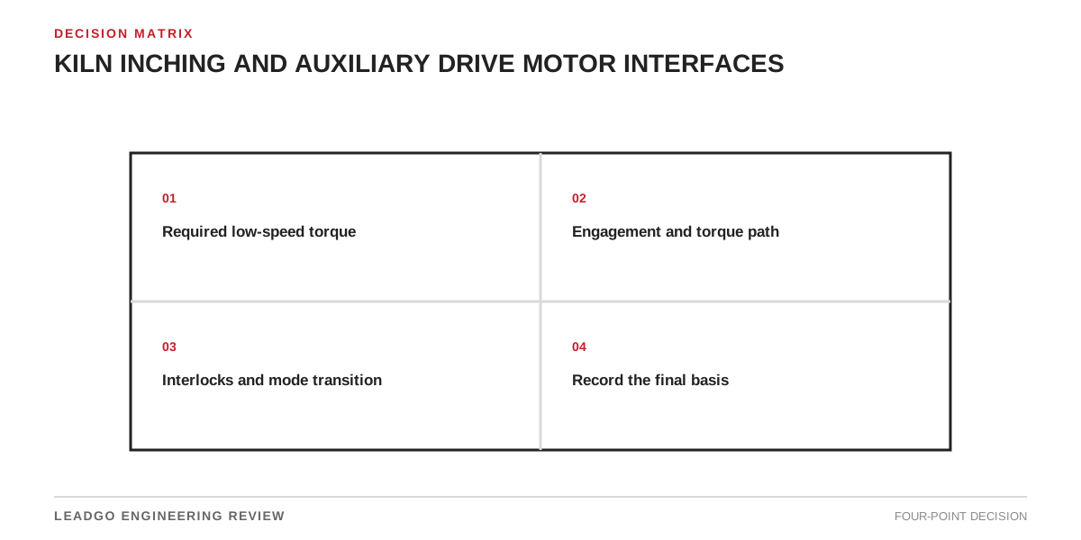
An inching drive is not a small duplicate of the main motor. It is a temporary torque path for inspection, lining work and positioning. Selection begins with the stopped kiln and ends with a verified cause-and-effect sequence.
Establish the limiting case
Specify maximum breakaway torque at the gear interface, acceleration, inching speed, run time, starts per hour and whether material can remain in the shell. Apply gearbox and coupling efficiencies consistently.
| Condition | Decision | Evidence |
|---|---|---|
| Normal inching | Continuous torque and cooling | Torque-speed calculation |
| Loaded restart | Peak torque and duration | Process-defined breakaway case |
| Power loss | Hold or controlled stop | Brake/backstop calculation |
| Main-drive transfer | No simultaneous torque | Cause-and-effect and feedback |
Check every shaft, clutch, coupling, gearbox and pinion in the path. The weakest component—not motor power—sets permissible torque.
Make engagement a proved state
A disengage command is not proof of disengagement. Define feedback, disagreement response and start permissives. The inching drive must also be blocked unless the main drive is isolated from torque production. Mechanical lockout remains separate from control interlocking.
Select motor, drive and brake together
Compare required torque-speed duty with motor and drive capability at site ambient and elevation. Low speed may reduce self-ventilation; frequent starts may govern temperature. State whether the brake merely holds or must absorb stopping energy.
Witness engagement, both permitted directions, stop, emergency stop, power failure and attempted unsafe transfer. Record current, speed, brake timing and feedback states.
Related reading: motor starting methods and acceleration time versus stall time.