
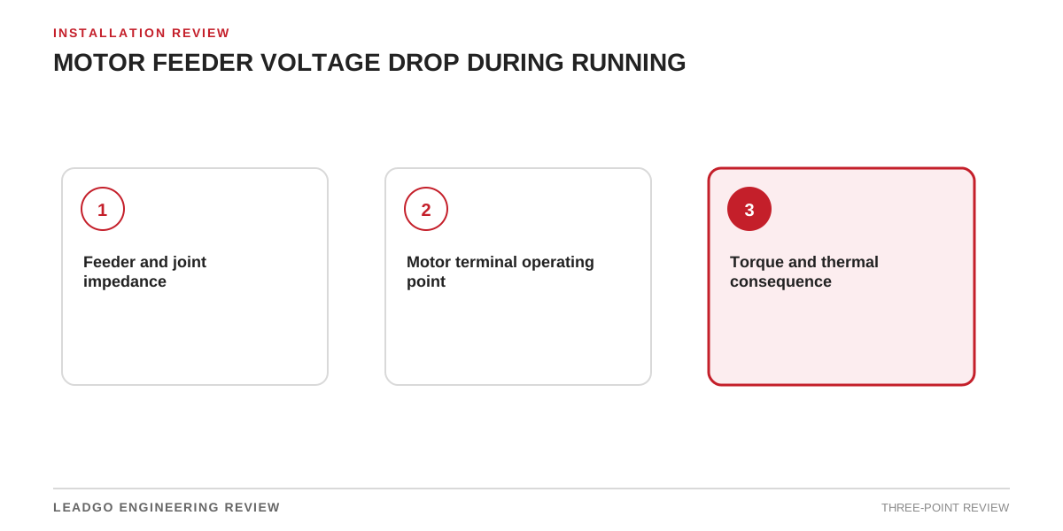
The motor responds to the voltage at its terminals, not the value printed on the upstream switchboard. A long route, warm conductors, joints and contact resistance can reduce terminal voltage and create unequal phase conditions.
Calculate the complete path
For a balanced three-phase screening calculation:
Voltage drop = √3 × current × (R cosφ + X sinφ) × route length
Use the project’s units and cable data consistently. Include parallel runs, conductor operating temperature, transformers, isolators and significant joints. The final design should follow the applicable electrical standard and project method.
| Input | Source | Check |
|---|---|---|
| Running current and power factor | Motor/load study | Represents the required operating point |
| Conductor R and X | Approved cable data | Correct size, material and temperature |
| Route length | Installed route | One-way length and parallel-run treatment are clear |
| Upstream voltage | Network study or measurement | Same load condition as the motor case |
| Joint/contact condition | Commissioning or maintenance evidence | No abnormal phase-specific drop |
Validate at the terminals
Measure phase voltages and currents under representative process load using the approved safe procedure. Time-align upstream and terminal readings if the supply itself varies. Keep individual phase values; an average can hide a poor joint or unbalance.
If measured drop exceeds the model, inspect terminations, isolators, fuses and contactors before changing the motor rating.
Review the motor consequence
Confirm available torque, current, temperature and protection margin at the predicted terminal condition. A cable that passes ampacity can still leave inadequate motor voltage.
Compare with motor voltage unbalance and the separate starting-voltage-drop review.