
Buyers see two temperature figures on a nameplate, notice that one of them is a class lower than the other, and ask what happened to the difference. Class F insulation with a Class B rise looks like a specification someone downgraded on the way out of the factory. It is the opposite, and the arithmetic takes about a minute.
The short answer
The two figures answer different questions. Insulation class describes what the winding materials withstand. Rise class describes how hard the design is allowed to work them. Putting Class F materials under a Class B rise limit means the designer declined to use part of the thermal capability the materials already have, and what he left behind is margin.
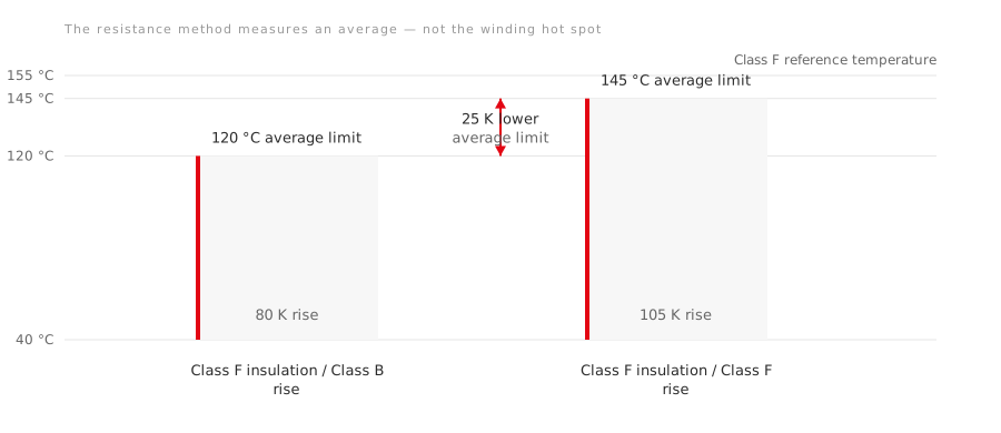
At the standard 40 °C ambient, the resistance method limits the average winding temperature to 120 °C for Class B rise and 145 °C for Class F rise. The useful comparison is therefore a 25 K reduction in average winding temperature. The often-used rule of ten suggests that this can slow thermal ageing substantially, but it does not turn into a whole-motor life guarantee.
The arithmetic
Two standards set the numbers, and they do not overlap.
| Class B | Class F | Class H | |
|---|---|---|---|
| Insulation class temperature, IEC 60085 | 130 °C | 155 °C | 180 °C |
| Rise limit by resistance, IEC 60034-1 | 80 K | 105 K | 125 K |
The resistance method reports an average winding temperature, not the hottest point inside the winding. Ambient plus rise therefore gives the permitted resistance-derived average; the insulation-class temperature is a reference for the thermal capability of the insulation system:
- F insulation, F rise: 40 + 105 = 145 °C average winding limit.
- F insulation, B rise: 40 + 80 = 120 °C average winding limit — 25 K lower than F rise.
- H insulation, F rise: 40 + 105 = 145 °C average winding limit.
The arithmetic gaps to the respective insulation-class reference temperatures are 35 K for F/B and 35 K for H/F. Those gaps include the difference between the resistance-derived average and the winding hot spot; they should not be presented as 35 K of freely spendable site margin.
The same rise limits appear in the American standard, where MG 1 gives 80 °C for Class B and 105 °C for Class F by resistance at rated load. Two standards systems, written independently, landing on the same numbers is a reasonable sign the numbers are not arbitrary.
What the margin is worth
IEC 60085 fixes the reference point: an insulation system held continuously at its class temperature reaches a life expectancy of 20,000 hours. That is the definition of the class, not a prediction about your motor.
From there the rule of ten does the rest. It is an approximation, not a clause in a standard, but it has a standards-grade corroboration: MG 1 states that running at the service factor temperature rise values, which sit exactly 10 K above the rated-load values, ages the insulation at approximately twice the rate. Ten degrees, two to one, from a standards body rather than a rule of thumb.
Applied to the two Class F cases above, and holding the actual hot-spot difference and every other ageing influence equal:
| Design | Winding temperature | Insulation life, relative |
|---|---|---|
| F insulation at F rise | 145 °C average limit | baseline |
| F insulation at B rise | 120 °C average limit | roughly 5 to 6 times the thermal-endurance baseline |
Take the multipliers as orders of magnitude rather than warranty terms. They describe thermal ageing of the insulation and nothing else.
F/B and H/F are the same trade
An F/B design and an H/F design each show a 35 K arithmetic gap between the resistance-derived average winding limit and the reference temperature of the insulation class. That makes the two specifications comparable in one narrow respect. It does not establish equal hot-spot temperature, equal life or equal design quality without test data for the actual machines.
Neither is a better motor by virtue of the letters. When you compare two quotations, compute the margin and compare that. Two plates reading “H” and “F” in the insulation field tell you nothing until you also read what rise each is held to.
The margin has somewhere to go
The lower rise gives useful headroom, but site conditions can consume it:
- Ambient above 40 °C. Every degree of ambient above the reference comes straight out of the margin. Equipment rooms, enclosed skids and hot process areas sit above it more often than the specification assumes.
- Altitude. Thinner air cools less well, and the derating is real above roughly 1000 m.
- Inverter supply. Harmonic content adds losses the sinusoidal test never saw, and low-speed operation reduces the airflow of a shaft-mounted fan while the losses stay.
- Restricted cooling. A blocked fan cover, a wall too close to the intake, or a fouled finned frame all show up as rise.
- Voltage unbalance. A small unbalance produces a disproportionate negative-sequence current and heats the winding for nothing.
A motor specified F/B and installed in a 55 °C room with a partly blocked cowling cannot be assumed to retain its standard rating. The lower rise helps, but the manufacturer still has to confirm the rating for the actual ambient, altitude, supply and cooling conditions.
The honest limit
Insulation life is rarely the thing that ends a motor. Bearings, contamination, moisture ingress, a supply transient or a mechanical failure usually arrive first, and none of them are helped by thermal margin.
The value of F/B is narrower and more practical than “five times the motor life”. It lowers the permitted average winding temperature at rated load and gives the insulation system more thermal headroom. How much of that remains in service depends on the actual hot spot and installation conditions.
What to ask for
- Both figures, stated separately: the insulation class and the temperature rise class, not one letter standing in for both.
- Which method determined the rise. Resistance and embedded-detector values are not interchangeable, and the tables differ.
- The ambient the rating assumes, which is 40 °C unless stated, and the altitude.
- For an inverter-fed machine, whether the rise figure was established on a sinusoidal supply or an inverter one.
A supplier who can answer those four without going away to check has thought about the thermal design. A nameplate carrying a single letter in the temperature field is the one to ask about.
Related: What a 1.15 service factor actually permits · Same motor, different grid: 50 Hz and 60 Hz · Motor duty types S1 to S10 · Why oilfield motors run hot