
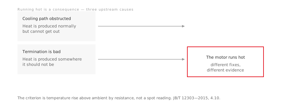
“The motor is running hot” is a symptom that gets treated as a diagnosis. It is neither — it is a consequence, and there are only three places the cause can be.
Direct answer
Heat has to leave the machine as fast as it is produced. Overheating means one of three things has changed:
- The cooling path is obstructed — heat is being produced normally but cannot get out.
- A termination is bad — heat is being produced somewhere it should not be.
- The duty or the supply is not what the machine was specified for — more heat is being produced than the design allows.
They have different fixes and different evidence. Working out which one you have is the whole job.
First, establish whether it is actually too hot
This is the step most often skipped, and the reason is that the usual test — whether someone can keep a hand on the frame — measures nothing.
The product standards do not limit temperature. They limit temperature rise above ambient, measured by the resistance method, which reads the average temperature of the whole winding rather than a spot on the outside of the enclosure. On the flameproof and increased-safety series used in oilfield service, the stator winding rise is limited to not more than 80 K, and the bearings are limited separately at not more than 95 °C for rolling bearings.
A frame reading of 75 °C means one thing in a 15 °C ambient and something else entirely at 45 °C on a summer lease. An infrared gun does not carry that context; a rise measurement does.
The F-to-B margin. These series use class 155 (F) insulation but are assessed against the 130 (B) rise limit. That is not a mismatch — it is deliberate headroom. The materials are rated higher than the machine is permitted to run, and the gap between the two is design life. A winding that lives below what its insulation can take does not spend life on ordinary excursions.
Path one: the cooling path
Externally cooled machines depend on air moving over the frame, and that dependency is invisible until it fails. The things that break it are unglamorous:
- Debris in the fan cowl. A cover packed with dust, fibres or windblown material stops the air before it reaches the fins.
- Fouling on the frame. Caked process material, mud or scale is thermal insulation applied to the outside of a heat exchanger. On a well site, cooling passages filling with gritty mud is a routine finding rather than an exotic one, and the fix is periodic flushing rather than diagnosis.
- Installation. A machine mounted too close to a wall, or drawing its cooling air from something else’s exhaust, is starved from day one and will never show a fault.
The tell for this path is that the machine heats uniformly and gradually, and that the fault is on the outside of the motor rather than inside it.
Path two: the terminations
This is the one thermal imaging is genuinely good at, and it is worth understanding why.
An oxidised or under-torqued terminal has resistance that the rest of the circuit does not. Current through that resistance produces heat exactly there. So a bad connection shows as a local hot spot on the termination, while the machine itself may still be within its rise limit. Re-torquing to the specified value removes the hot spot and the temperature drops.
Two practical consequences:
- Survey the connections, not only the machine. A thermal survey that photographs the frame and skips the terminal box misses this entire failure mode.
- It is a schedule item. The condition develops over months and is invisible to anything except temperature until the joint fails.
Where the motor is a flameproof machine, this check has a second dimension: the terminal box is part of the protection, so its covers, seals and fastener torque are not ordinary maintenance items. See how to verify an explosion-proof motor certificate for what the documentation should already tell you about those conditions.
Path three: the duty, and the supply
If the cooling path is clear and the connections are sound, the machine is being asked to produce more heat than it was designed to lose:
- The duty is not what was stated. A cyclic load specified as continuous duty is the standard version of this. Starting and braking heat is real heat — see motor duty types S1 to S10.
- The supply has drifted. Voltage and frequency deviation is permitted within limits, but performance inside those limits is not guaranteed to match the rated figures.
- A drive was added without matching it. Additional harmonic losses raise winding temperature, and a shaft-mounted fan turning slowly cools progressively worse at exactly the speeds where torque is still full.
- The machine is stopped but energised. Self-cooling stops when the shaft stops.
On a flameproof machine this path has a compliance consequence as well as a life consequence: surface temperature is what the temperature class limits, so anything pushing it up is attacking a certified specification rather than merely shortening life. That mechanism is set out in motor temperature classes T1 to T6.
The insulation resistance check, and the trap in it
Insulation resistance is the standard field check after a hot event, and it is easy to apply the wrong number.
JB/T 12628—2016 gives the criteria in clause 4.15, in two states:
| State | Limit |
|---|---|
| Cold, at 40 °C | Not less than 5 MΩ |
| Hot, or after a heat run | 0.38 MΩ at 380 V · 0.66 MΩ at 660 V · 1.14 MΩ at 1140 V |
Two things to note about using them.
The hot and cold criteria are not interchangeable. The same standard’s inspection rules allow a cold measurement during routine testing, but only on the condition that the hot value would still comply. A cold reading is therefore a proxy, not a substitute — a winding that has taken up moisture can read acceptably cold and fail hot.
Do not borrow a figure from the damp-heat test clause. The type-test clauses in the same standard cover a different question — whether the design survives cyclic humidity — and their values are not a field acceptance criterion. Using one as if it were is permissive by roughly a factor of four, which is precisely the direction an error should not go.
If the reading is below the limit, dry the winding at a temperature not exceeding 120 °C and measure again rather than energising it.
What to do, in order
- Measure the rise, not the temperature. Ambient and a resistance-method reading, or at minimum ambient recorded alongside whatever you did measure.
- Look at the cooling path. Cowl, fins, frame, air supply, mounting clearance.
- Thermally survey the terminal box, not just the machine. Re-torque to specification if anything is warm.
- Check insulation resistance against the right clause, in the state you measured it in.
- Then question the duty and the supply — and if a drive has been added, question the cooling arrangement, not just the drive settings.
A manufacturer can tell you the rise limit, the bearing limit and the insulation criteria for a specific machine, and those figures belong in the maintenance procedure rather than in an engineer’s memory. For the flameproof series used in this service, they sit in the product standard and the manual for the specific series — ask for both alongside the hazardous-area range rather than after something has already run hot.
Going deeper
- Motor duty types S1 to S10 — where cyclic heat is defined, and why the default duty assumption is wrong for oilfield loads
- Motor temperature classes T1 to T6 — why surface temperature is a certified specification on a flameproof machine
- Oil well pump motors: why NEMA Design D is specified — the cyclic derating that this article’s path three refers to