
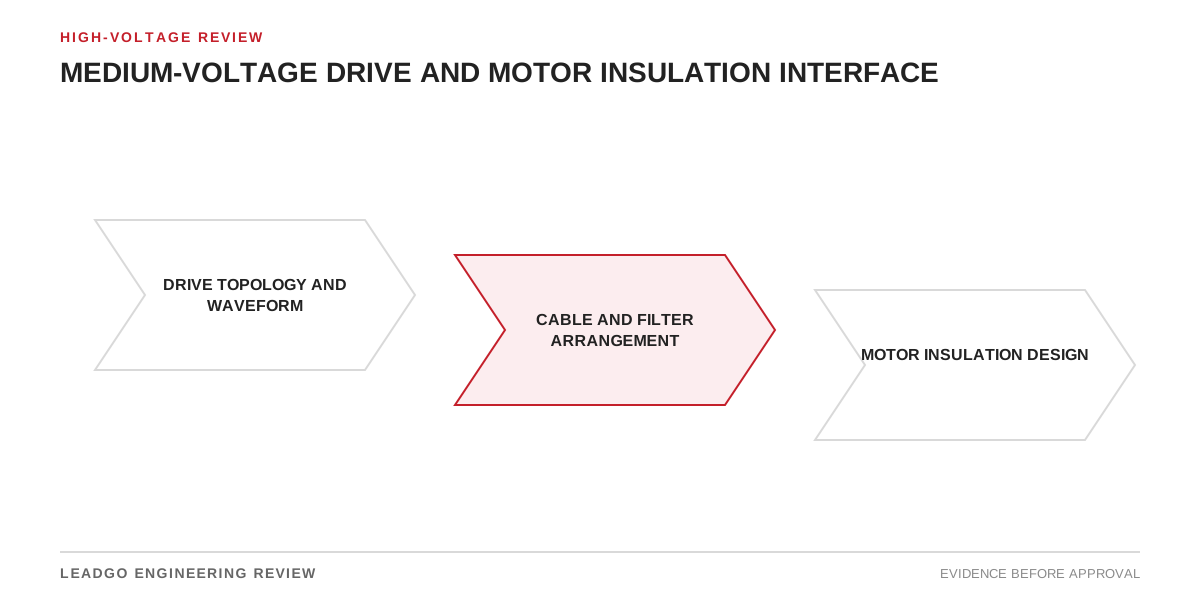
The voltage printed on a medium-voltage drive and the voltage stress seen by the first turns of a motor winding are not the same engineering quantity. Converter topology, switching pattern, output filtering, cable propagation, grounding and motor winding construction shape the waveform that reaches the terminals. Procurement teams therefore need a coordinated system statement, not separate “compatible” declarations from vendors working with different assumptions.
This review identifies the data that must cross the drive, cable and motor package boundaries before the insulation system is approved.
Applicability and interface boundary
Use this method for medium-voltage motors supplied from variable-frequency drives, including new packages, drive retrofits to existing motors, cable-route changes, output-filter changes and projects that substitute a drive topology after motor selection.
The article does not prescribe one universal peak voltage, rise time, partial-discharge limit or cable-length threshold. Those values depend on topology, voltage level, modulation, filter, cable and insulation design. The governing project specification, applicable standards and written supplier limits control the final decision. Specialized waveform and partial-discharge assessments require suitable instruments and expertise.
Define the physical boundary from the drive output terminals through reactors, filters, switchgear, cable and terminations to the motor winding and grounding system. Also define the operating boundary: minimum and maximum speed, switching settings, overload, regeneration, bypass, number of motors and cable configurations.
Drive–cable–motor insulation interface matrix
| Interface item | Drive/filter supplier returns | Motor/cable input required | Acceptance output |
|---|---|---|---|
| Converter topology | Cell or bridge arrangement and output principle | Motor voltage and winding connection | Named topology basis |
| Output waveform | Expected terminal-side levels, rise behavior and switching conditions | Motor insulation limits | Coordinated waveform statement |
| Output filter | Type, location, ratings and operating restrictions | Cable and motor parameters | Filter duty and guarantee boundary |
| Cable | Permitted length/configuration and model assumptions | Actual type, length, parallel runs and terminations | Approved cable schedule |
| Motor winding | Required converter-fed insulation capability | Actual waveform envelope | Design compliance statement |
| Grounding | Drive transformer, neutral and shield requirements | Site grounding arrangement | Approved grounding diagram |
| Common-mode path | Common-mode control and mitigation features | Bearings, shaft grounding and PE path | Bearing-current mitigation plan |
| Switching settings | Frequency or pattern assumptions and permitted range | Noise, loss and thermal constraints | Locked parameter window |
| Operating speed | Frequency and voltage range | Motor cooling and mechanical limits | Approved speed-duty envelope |
| Regeneration | Expected dc-link and output behavior | Load overhauling/deceleration duty | Regenerative duty statement |
| Multiple motors | Output arrangement and isolation restrictions | Individual cable and motor data | Approved topology or prohibition |
| Verification | Calculation and measurement method | Terminal access and sensor limits | Factory/site acceptance plan |
Every row should have a document owner and revision. “By others” is not a technical disposition if the missing party controls a decisive input.
Characterize the drive output correctly
Start with the actual converter topology. Different architectures produce different numbers of voltage levels, switching behavior, common-mode content and filtering needs. Obtain the supplier’s waveform description and the conditions under which its limits apply. A marketing phrase such as “near sinusoidal” is not a substitute for an engineering envelope.
Define where each voltage is referenced and measured: phase-to-phase, phase-to-ground, drive output or motor terminal. Record peak, repetitive behavior, rise characteristics and fundamental voltage separately. Include tolerances, switching settings, input-voltage range and relevant operating points.
If an output reactor, dv/dt filter or sine-type filter is included, obtain its guaranteed boundary, losses, thermal duty, resonance restrictions and permissible cable range. Confirm whether the drive control parameters are constrained by that filter.
Include the real cable and grounding arrangement
Cable length alone does not describe the transmission path. Record conductor arrangement, insulation, shield, grounding method, parallel runs, intermediate switchgear, junctions and termination details. A design reviewed with one cable model should not be extended to a different route without assessment.
The protective-earth and shield path affects common-mode current and electromagnetic behavior. Coordinate shield bonding, grounding conductors, drive transformer arrangement, motor frame grounding and any shaft-grounding device. The insulation review and bearing-current review are related, but one does not replace the other.
Where output contactors or isolators are used, define permitted switching states. Opening or closing a motor circuit on an energized drive output can create risks that depend on the selected drive and switching equipment. Use the supplier’s approved sequence.
Match motor insulation and winding evidence
The motor supplier needs the drive waveform envelope, not merely rated voltage and frequency. Request the insulation-system classification or qualification basis relevant to converter-fed operation, winding construction, turn and groundwall design basis, terminal arrangement and any restrictions on cable or filtering.
For an existing motor retrofit, collect nameplate and winding records, insulation history, prior repair information and original supply duty. “High-voltage motor” does not prove converter compatibility. If design evidence is unavailable, define the engineering assessment and risk controls rather than converting uncertainty into an unsupported approval.
Also review winding thermal duty. Harmonic content and cooling at reduced speed can affect temperature even when insulation voltage stress is acceptable. Separate the electrical-insulation question from thermal, vibration, torsional and mechanical-speed limits, then close all of them in the system review.
Common interface failures
- Approving the motor from drive rated voltage alone.
- Using waveform data measured at the drive instead of the motor terminal.
- Calling an output “sinusoidal” without a defined tolerance and operating range.
- Treating all multilevel drive topologies as equivalent.
- Changing cable length, type or parallel arrangement after approval.
- Omitting phase-to-ground and common-mode behavior.
- Selecting a filter without checking resonance, losses or control restrictions.
- Assuming an inverter-duty label covers an undefined medium-voltage waveform.
- Ignoring an existing motor’s repair and insulation history.
- Leaving switching frequency adjustable outside the reviewed range.
- Reviewing insulation while overlooking low-speed cooling and overload duty.
- Dividing responsibility among vendors without one coordinated compliance statement.
Decision steps for insulation coordination
- Freeze the one-line and identify every component between drive and winding.
- Record converter topology, control method and switching parameter range.
- Define the required speed, torque, overload, braking and regeneration envelope.
- Obtain the predicted motor-terminal waveform for the actual cable arrangement.
- Establish cable, filter and grounding models and their revision.
- Obtain motor insulation limits and converter-fed qualification evidence.
- Compare waveform stress with the motor design on matching definitions.
- Review common-mode current and bearing-current mitigation separately.
- Check filter thermal duty, resonance restrictions and drive settings.
- Define factory and site verification without imposing unsuitable tests.
- Allocate guarantees and interfaces in a signed compliance schedule.
- Lock parameters and installation details that the conclusion depends on.
Use sensitivity cases when cable length, source voltage, switching setting or operating point varies. A design that passes only one nominal configuration needs a clear installation restriction.
Supplier and RFQ information requirements
Ask the drive supplier for topology, output waveform envelope, measurement definitions, switching range, common-mode information, filter requirements, cable-model assumptions, maximum approved configurations, regeneration behavior, output-switching restrictions and parameter limits. Require model files or calculation reports where these are contractual deliverables.
Ask the cable supplier for construction, electrical parameters over the relevant frequency range where needed, length tolerance, shielding, grounding and termination information. Ask the motor supplier for converter-fed insulation evidence, applicable waveform limits, winding and terminal design basis, cooling duty, temperature-rise basis, bearing-insulation or shaft-grounding provisions and restrictions on drive settings or cable.
The RFQ should name the party responsible for the integrated study and final compatibility statement. Separate supplier letters are insufficient when their assumptions do not match.
Verification and interface closeout
Close the interface when the actual drive topology, parameters, filter, cable, grounding and motor design match the reviewed configuration; terminal-waveform definitions are consistent across suppliers; the motor insulation evidence covers the stated envelope; thermal and common-mode issues have separate dispositions; and prohibited configurations are captured in drawings and settings.
The acceptance plan may include document review, model validation, factory waveform evidence or site measurement as agreed. Site measurement must define probes, bandwidth, grounding, location and safe access; an unsuitable measurement setup can be hazardous and misleading.
Archive the coordinated study, supplier limits, cable schedule, filter data, final parameters and test records. Reopen the review after changes to drive power hardware, modulation, switching settings, filter, cable, grounding, motor winding, operating speed range or regenerative duty.