
The request usually arrives as a product question — induction or permanent magnet. On a retrofit it is the wrong first question, because a variable-speed installation is five parts and the motor is one of them.
Direct answer
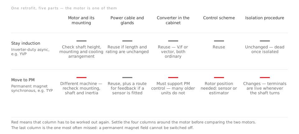
An existing drive project hands you five things: the machine and its mounting, the power cable, the converter in the cabinet, the control scheme, and the isolation procedure.
Replacing an inverter-duty induction motor with a similar one touches the first column and leaves the rest largely alone. Replacing it with a permanent magnet synchronous machine puts four of the five back in play.
That is the decision. The comparison between the two machine types only becomes relevant once you know which of those columns you were going to reopen anyway.
The converter is the gate, and it is answerable today
Ordinary industrial practice for an induction motor is scalar constant-V/f control, which can be implemented open-loop — no feedback of any kind. That is what a large share of installed general-purpose drives do, and it is why an induction motor is so forgiving in a retrofit: the drive does not need to know anything about the rotor.
A PM synchronous machine does. Commutation has to be timed to rotor position, taken either from position sensors or estimated from motor parameters such as the EMF. A drive without that capability cannot start or control the machine — not badly, but at all.
So the first question on the list is not about motors:
Does the converter already in the cabinet support permanent magnet control? It is a yes or no answer, it is in the drive manual, and it decides most retrofits before any motor is compared.
If the answer is no, then a PM retrofit is a motor plus converter project. That may still be right — but it is a different budget and a different scope, and calling it a motor swap is how retrofits go wrong.
Where the cabinet is being renewed anyway, this gate disappears and the choice becomes a genuine one. LEADGO supplies the LD800 variable-frequency drive alongside both motor lines for exactly that case.
The isolation procedure, which is the part most often missed
A spinning machine produces back electromotive force — the same generator action that makes a generator work. In an induction motor the rotor field collapses once the supply is removed, so an isolated machine is dead even if the shaft is turning.
A permanent magnet rotor cannot be switched off.
| Induction machine | PM synchronous machine | |
|---|---|---|
| Supply open, shaft still | Terminals dead | Terminals dead |
| Supply open, shaft turning | Terminals dead | Terminals live |
The second row is a real condition, not a theoretical one. A fan windmilling in a duct, a pump turned by reverse flow, a conveyor being turned by its load — any of these turns an isolated PM motor into a generator feeding its own terminal box.
The consequence is procedural. Isolate and lock the supply stops being sufficient; the shaft has to be stopped and held as well, and that has to be written into the permit rather than remembered. If the site’s lock-out procedure will not be revised, that is a genuine argument for staying with an induction machine — and it is a better argument than any efficiency figure, because it is about whether the installation can be maintained safely by the people who will actually maintain it.
Speed range, and what it costs on each machine
Both machines behave the same way in principle. Below base speed the drive holds flux and you get constant torque; above base speed, raising speed means reducing flux density — field weakening — and torque falls away.
The YVP inverter-duty induction series is specified with a constant-torque range of 5 – 50 Hz and constant power from 50 to 100 Hz, which is the shape most retrofits need: the mains frequency stays the base point and the range is built around it.
The difference is what field weakening costs. On an induction machine the flux comes from the stator anyway, so weakening it is simply a matter of reducing it. On a PM machine the rotor field is fixed, and weakening it means pushing current that does no useful work for as long as you stay up there. A PM machine that spends its life above base speed is being asked to do the thing it is least suited to.
The practical version: where the load actually sits decides this, not the top of the range. A load that lives below base speed at part load suits a PM machine well. A load that lives above it does not.
Where the saving really came from
It is worth being blunt about this, because retrofit proposals are rarely blunt about it.
The large energy reduction on a fan or pump came from putting a drive on it at all — from being able to run slower when the load allows, where power falls as the cube of speed. If the project already has a drive, that step has been taken.
Moving from an inverter-duty induction motor to a permanent magnet one adds a further gain in the machine itself, and it is largest exactly where these loads live — at part load, which is the argument made in detail in permanent magnet versus induction in oilfield duty. But it is an increment on an improvement already made, not a repeat of it.
Two things follow. First, a payback calculated against a fixed-speed baseline is answering a question you already settled. Second, the figure that matters is measured at the operating points the load actually uses — which is available, because the converter-fed test standard derives losses at any load point from seven measured ones.
The failure mode that has no induction equivalent
A magnet’s resistance to a reversing field is its coercive force, and it falls as temperature rises. A severe overload, a terminal short or a sustained over-temperature can push the operating point past the point of return.
What makes this a retrofit consideration rather than a footnote is the repair path. A damaged induction rotor is often a rewind or a replacement of a standard part. A partially demagnetised PM rotor is a new rotor, and the machine’s performance may be quietly lower rather than obviously broken. On a line where downtime is the real cost, ask what the spares arrangement is before the machine is ordered, not after.
None of this makes PM the wrong answer. It makes it a decision with a maintenance tail attached, and retrofits are where maintenance tails get discovered.
What to settle, in order
- Does the existing converter support PM control — from the drive manual, before anything else.
- Will the isolation procedure be revised to cover a shaft that can turn. If not, the question is closed.
- Where the load actually operates — mostly below base speed, or above it.
- The mechanical interface — shaft height, mounting, coupling and inertia, which a change of machine type can change.
- The spares and repair path, including who holds a rotor.
- Only then, the two machines, compared at the operating points from step 3.
LEADGO builds both lines — the YVP variable-frequency induction series and the TYP permanent magnet variable-frequency synchronous series. The useful first message on a retrofit is the list above rather than a rating, because with those six settled the machine choice is usually already decided, and with them unsettled no rating helps.
Going deeper
- Permanent magnet versus induction in oilfield duty — the part-load case for PM, worked through on a real duty cycle
- Line-start PM motors — PM efficiency where there is no drive to retrofit
- Interior versus surface magnet rotors — salience, overload capability and how much field weakening is usable
- Drive system efficiency, IE and IES — classifying the whole installation rather than the motor
- VFD reactors and filters — the other three places a retrofit runs into trouble