
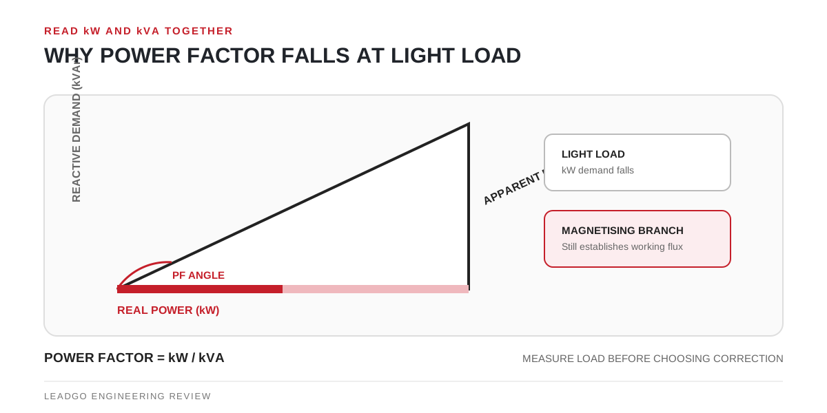
A lightly loaded induction motor can show a disappointing power factor even when nothing is broken. The shaft is asking for less real power, but the machine still needs magnetising current to establish its working flux. The result is a larger reactive share of the current seen by the supply.
Separate power factor from efficiency
The two terms answer different questions:
| Measure | Relationship | Practical question |
|---|---|---|
| Power factor | real power divided by apparent power | How effectively is supply current being converted into real electrical power at this point? |
| Motor efficiency | shaft output divided by motor input | How much input power becomes useful shaft output? |
| Load factor | actual output compared with rated output under a defined method | How much of the motor’s rated mechanical capability is being used? |
A motor may have low power factor at light load without the same proportional fall in efficiency. Conversely, a satisfactory power-factor reading does not prove that the driven system is efficient. IEC 60034-2-1:2024 defines standard methods for determining efficiency and specific losses; a casual field ratio is not a substitute for those test methods.
Check the meter reading with a transparent calculation
For a balanced sinusoidal three-phase supply, apparent power can be calculated as:
Apparent power (kVA) = √3 × line voltage (kV) × line current (A)
Then:
Power factor = real power (kW) / apparent power (kVA)
Take an illustrative 400 V case with 20 A line current and 8.0 kW measured real input:
- apparent power = 1.732 × 0.400 × 20 = 13.86 kVA;
- power factor = 8.0 / 13.86 = 0.58.
This calculation checks the scale of the reading; it does not identify the cause or the shaft load. If the motor is supplied by a drive or the waveform contains material harmonics, confirm whether the instrument reports true power factor, displacement factor or another quantity. Use an instrument and method suitable for the waveform.
Build a load profile before choosing a remedy
The U.S. Department of Energy’s motor-load guidance recommends measurement-led evaluation rather than assuming load from the nameplate. Record representative points, not only the quietest or busiest minute:
- line voltage, current, real power, apparent power and reported power factor;
- production state or process output at the same timestamp;
- starts, idle periods and operating hours in each state;
- whether the motor is mains-fed, bypassed or supplied through a drive;
- motor rated data and the method used to estimate shaft load.
This profile distinguishes a motor that is briefly idle by design from one that spends most of its life substantially oversized for the duty.
Choose the intervention at the correct boundary
| Evidence pattern | First engineering question | Possible path to evaluate |
|---|---|---|
| Long idle operation with no process need | Can the machine be stopped safely when production is absent? | Controls or operating-sequence change |
| Persistent light load with stable process demand | Was the motor sized for a rare peak or future case? | Duty study and right-sizing review |
| Cyclic peak requires present motor capability | Can the process be buffered or controlled differently? | Load management or drive/application review |
| Plant-level reactive demand remains high | Where should correction be switched and protected? | Power-system study for central, group or local correction |
| Drive-fed input has unexpected readings | Is the meter measuring the intended quantity and waveform? | Drive and power-quality review |
DOE’s Energy Management for Motor-Driven Systems discusses motor loading and plant power-factor correction together. It also warns that capacitor application belongs to a system study that considers harmonics and switching. A capacitor selected from one motor’s light-load snapshot can create a different problem when equipment is stopped, switched or drive-fed.
Close the review with an economic and technical record
Before approving a motor change or correction equipment, keep the measured load profile, utility tariff or internal capacity objective, one-line diagram, harmonic information, switching philosophy and responsible electrical review. If right-sizing is proposed, also verify starting torque, acceleration, overload duty, ambient conditions and the future production case.
The useful outcome is not “power factor is low.” It is a traceable decision about where reactive demand originates, when it matters, and which boundary—operation, motor selection or distribution system—can change without compromising the duty.