
“Which motor for an oil well?” has three answers, and the gap between them is not horsepower. Each lift method presents a different load shape, and the load shape is what selects the machine.
Direct answer
| Beam pump (sucker rod) | Progressing cavity pump | Electric submersible pump | |
|---|---|---|---|
| Where the motor is | Surface, on the unit | Surface, on the wellhead | Downhole, in the casing |
| Load character | Cyclic, two torque peaks per stroke | Continuous, near-constant torque at low speed | Continuous, centrifugal |
| What selects it | Slip and starting torque | Torque, speed control, backspin capacity | Diameter, and fluid cooling |
| Typical machine | High-slip induction, or PM semi-direct drive | Surface drive: direct or right-angle, usually on a VFD | Two-pole squirrel-cage induction, ~3,500 rpm at 60 Hz |
| The failure mode that defines it | Cannot start what it can run | Backspin when power is lost | Pulling the well to reach it |
Beam pump: sized for starting, not for running
The load is the one we set out in why NEMA Design D is specified for oil well pumps — a reciprocating cycle with a peak when the rod string and fluid column lift, and another when the counterweight lifts.
The petroleum engineering literature lists four motor designs in oilfield pumping service, and they line up on one axis:
| Design | Rated slip | Starting behaviour |
|---|---|---|
| NEMA C | about 4% | Fair starting torque |
| NEMA D | 5% to 8% | Higher starting torque than NEMA C |
| NEMA D extended | 8% to 13% | Higher again |
| Special-purpose ultra-high slip | up to about 30% | Superior starting, electrical and mechanical characteristics |
More slip means the rotor gives up more speed under a peak, so the peak is absorbed mechanically rather than drawn from the line.
The sizing rule that matters is easy to miss. Empirical equations scale hydraulic horsepower up to a prime mover rating with a term for the extra losses arising from the cyclic nature of the load — an adjustment the literature says is not easily estimated, and is made from experience. Then comes the constraint:
The prime mover must be large enough to start the unit without the assistance of system inertia.
On conventional units with long strokes relative to their gearbox size, this initial loading can reach the point where a motor big enough to run the unit is not big enough to start it. That is why a power-table lookup produces oversized motors that still stall on start: the table answers the wrong question.
One piece of context that speeds up any conversation with a pumping-unit vendor: the API unit rating is a three-part code. A unit marked 160-173-64 has a gear reducer rated 160,000 in-lb of torque, a structural capacity at the polished rod of 17,300 lbf, and a maximum stroke of 64 inches.
Progressing cavity pump: constant torque, plus a hazard the beam pump does not have
A PC pump is a helical rotor turning inside an elastomer stator. The load is continuous and close to constant torque at low speed, which is a far simpler thermal picture than a beam pump — and the reason PC systems reach 50% to 70% overall efficiency, higher than any other major artificial lift type.
The trade is a set of constraints:
- Maximum production around 800 m³/d (5,000 bbl/d)
- Maximum lift around 3,000 m (9,800 ft)
- Maximum temperature around 170 °C (330 °F)
- Elastomer compatibility with the produced fluid
That last one has a direct motor consequence. Produced fluids swell, soften, shrink or harden the stator. Swelling tightens the rotor/stator interference fit, and the torque needed to overcome that fit can exceed what the surface drive can deliver — at which point the drive is not undersized for the pump as designed, it is undersized for the pump as it has become. Friction at that interference fit also makes the pump’s internal operating temperature significantly higher than the reservoir fluid temperature.
Surface drives come in two arrangements. A right-angle drive transmits power through pinion gears and is generally used at lower horsepower; because it can be driven by a gas engine, it stays popular where the well site is not electrified. A direct drive has no internal gear reduction — power transmission and speed control run straight through belts and sheaves from the motor, or, in a vertical hollow-shaft machine, straight into the rod.
And then the hazard that defines the application: backspin. The rod string stores torsional energy in normal running, and on loss of power it unwinds and drives the system in reverse. Every surface drive carries recoil control for it — hydraulic disc braking, fixed orifice, vane or hydrodynamic systems. The braking capacity is part of the drive specification, not an accessory.
There is an industry product standard for the direct-drive flameproof PM machines used in this service — JB/T 12302-2015, for frame sizes 225 to 355. What it makes mandatory is a good checklist of what to ask for: the frame-size-to-torque-and-speed relationship, the back-EMF constant, guaranteed efficiency at rated voltage, speed and torque, and the axial load the motor can withstand. That last item exists because on a vertical hollow-shaft direct drive, the motor is carrying the rod string.
ESP: the motor is not a surface problem
The ESP prime mover is a submersible motor: two-pole, three-phase, squirrel-cage induction, running at a nominal 3,500 rpm at 60 Hz, sitting downhole and cooled by the produced fluid passing it.
ESP is the high-volume, high-depth option — applications to 13,000 ft TVD and beyond, flow rates to 60,000 BPD, installable in 4½-inch casing and larger, and usable in highly deviated wells onshore and offshore. Systems are highly efficient from about 1,000 BPD and can run as low as 200 BPD. They do best where gas, solids and excessive pressures are not present in quantity.
The reason it barely overlaps the other two: the binding constraint is diameter, not frame size; the cooling comes from flow rather than a fan; and maintenance means pulling the well. None of the surface-motor trade-offs above apply.
LEADGO does not build ESP systems in-house; where an application calls for one, supply runs through partner manufacturers. The comparison above is set out so the lift method gets chosen on load shape rather than on what a supplier happens to stock.
What to settle before asking for a quotation
- Which lift method, and therefore which load shape. This is step zero, and it changes everything downstream.
- For a beam pump: the starting condition, not just the running load. Ask what the motor must break away against.
- For a PC pump: the torque including the current state of the stator fit, the speed range, the axial load if the drive is vertical, and the backspin energy.
- The area classification, in all three cases. Wellsites are classified locations — see who classifies a hazardous area.
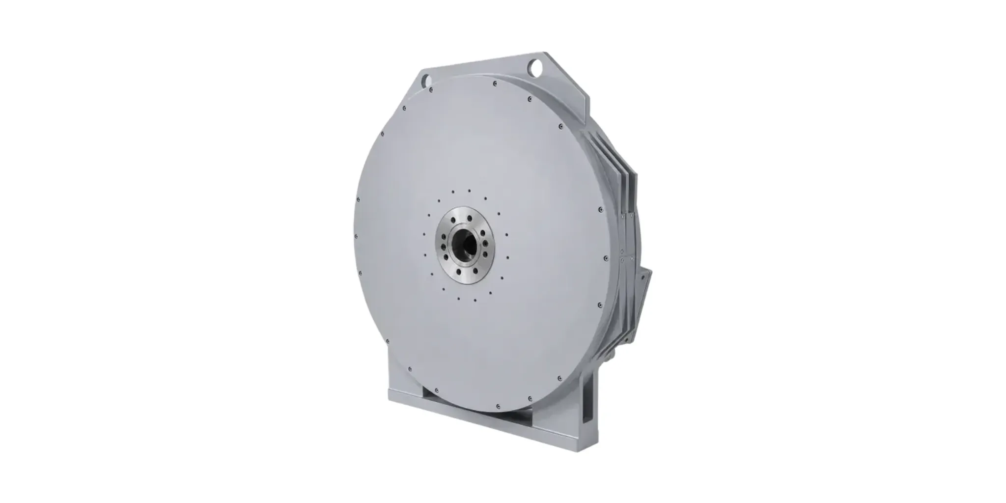
LEADGO builds CYJTYP for beam-pump semi-direct drive and TYPL — a vertical hollow-shaft flameproof permanent magnet machine with its drive cabinet — for progressing cavity pumps. Send the lift method and the starting condition, and the rest of the specification follows from them.
Going deeper
- Oil well pump motors: why NEMA Design D is specified — the beam-pump case in detail, including multi-rated motors and power factor
- How to size a motor for a beam pump — the three-step load calculation, and belt drive versus direct coupling
- Motor duty types S1 to S10 — why a cyclic load must not be specified as continuous duty