
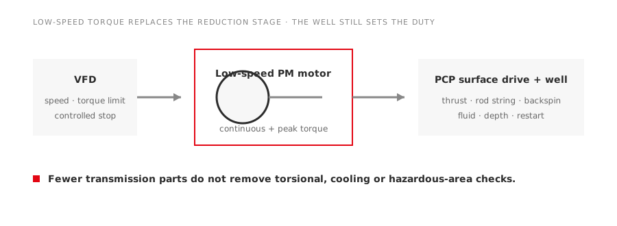
A conventional progressive cavity pump surface drive often uses a standard-speed motor and a belt or gearbox to obtain the low shaft speed required by the pump. A low-speed permanent-magnet direct drive changes that architecture by producing the required torque closer to the polish-rod speed.
The attraction is clear: fewer transmission components, controlled speed and a compact torque path. The engineering work also changes. The motor now sits closer to the well’s torsional and axial-load behavior, so a kW-for-kW substitution is not enough.
What the direct drive removes
Depending on the existing arrangement, a direct-drive system may remove belts, pulleys and a reduction gearbox. That can eliminate alignment points, belt tensioning, gearbox oil and transmission losses. It can also reduce the number of exposed rotating components.
It does not eliminate the surface-drive structure, thrust handling or well-service requirements. The project team must identify exactly which components disappear and which remain. “Gearless” should never be read as “maintenance-free.”
The TYPL series is intended for this low-speed PCP duty. Final selection still depends on the well and surface-drive interface.
Size from torque and speed
Power is torque multiplied by angular speed. At low speed, a modest power rating can correspond to substantial shaft torque. That is why the existing high-speed motor rating alone is an unreliable sizing basis.
Collect:
- normal and maximum operating speed;
- continuous torque and cyclic peak torque;
- breakaway and restart torque;
- polish-rod axial load and the component that carries it;
- well depth, fluid viscosity, solids and expected operating range;
- present gearbox or belt ratio and measured input current;
- starts, reversals and shutdown behavior;
- ambient temperature and solar exposure.
Where measured torque is unavailable, use a documented PCP model and validate it against operating records. Apply margins transparently rather than hiding them in an oversized power figure.
Check the torsional system
The rod string stores torsional energy. A trip, sudden speed change or reversal can release that energy and produce backspin. The direct-drive motor, coupling, brake or holding device, drive and control sequence must manage this behavior.
Ask how the system handles:
- controlled deceleration;
- loss of power;
- backspin and reverse speed;
- restart after a trip;
- torque limit and stall protection;
- resonant speed regions;
- emergency isolation.
A smooth steady-state torque curve does not prove that transient behavior is safe. The commissioning plan should include controlled stopping and restart tests within the equipment supplier’s procedure.
Match the motor and inverter
A drive-fed PM motor requires an inverter that supports the motor topology and has validated motor parameters. Stable no-load rotation is not sufficient proof. The system must demonstrate low-speed torque, current limiting, speed estimation or feedback, field-weakening limits where applicable and protection after a trip.
At very low speed, a shaft-mounted fan may provide little cooling. Confirm the motor’s cooling method and continuous torque at the minimum operating speed. Winding temperature protection and, where required, bearing-temperature monitoring should be included in the protection schedule.
Our PMSM buyer questions and VFD matching checklist cover these controls in more detail.
Treat hazardous-area approval separately
Oilfield installation does not by itself define the required protection. Use the site classification drawing and applicable jurisdiction. Verify gas group, temperature class, zone or division, equipment protection level, ambient range and certificate conditions for the exact motor-drive arrangement.
The motor may be installed in a classified area while the inverter is located in a non-hazardous enclosure or room. Cable entries, glands, grounding, sensors and local disconnects remain part of the compliance boundary.
Do not infer approval from a flameproof-looking enclosure or from an IP rating.
Calculate savings without a generic percentage
The energy comparison should separate three effects:
- motor efficiency at the actual torque and speed points;
- inverter loss across the operating range;
- transmission loss removed with the belt or gearbox.
Use measured input power for the existing system where practical. Build the proposed case from verified motor-drive data at comparable operating points. If the retrofit also changes speed or well production, report that process change separately so it is not confused with equipment efficiency.
Add maintenance items such as belts, gearbox oil, alignment, planned inspections and outage labor. Then include the new system’s bearings, cooling, drive support and spare strategy. A credible lifecycle model counts removed work and newly introduced work.
Mechanical integration questions
Confirm shaft interface, coupling, thrust path, mounting loads, overall height, lifting access and guarding. Review whether the existing base can accept the direct-drive torque reaction and mass distribution. Check cable routing and enclosure access for field maintenance.
The project should identify responsibility for the complete interface. A motor supplier can verify motor capability; the surface-drive or PCP system owner must confirm rod-string, thrust and well behavior.
Commission with a baseline
Before removing the original drive, record speed, current, vibration, temperature, production condition and maintenance history. After installation, trend speed, torque-producing current, temperature, trips and controlled stops over representative operating cycles.
The strongest direct-drive case is not a headline efficiency number. It is a traceable comparison showing that the new system meets the well’s torque and safety requirements while removing specific losses and maintenance tasks.
Plan the spare and service route
A conventional motor, belt and gearbox may be familiar to local technicians and supported by generic spares. A direct-drive package has fewer components but may concentrate risk in a specialized motor, inverter or bearing arrangement. List the parts that can be replaced locally, the parts that require factory service and the parameter files needed to commission a spare drive.
Keep an approved backup of motor and control parameters. Define how the well can be secured if the drive fails and how a replacement unit will be aligned and tested. Where production consequence is high, compare holding a complete spare package with holding selected electronic and mechanical modules. Simplifying the drive train is valuable only when the restoration plan is equally clear.
For a PCP retrofit, direct drive can simplify the mechanical chain. It also moves responsibility toward integrated motor, inverter and well control. Review that system as a whole before comparing purchase prices.