
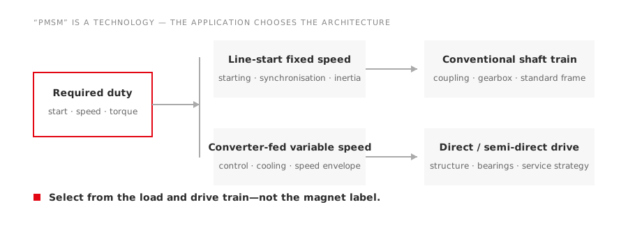
Permanent-magnet synchronous motor is a technology description, not a complete product specification. A pumpjack direct-drive motor, a line-start replacement and a high-speed blower motor may all use permanent magnets while requiring very different controls and mechanics.
Direct answer
Start with four questions:
- Must the motor start from the line, or will it use a converter?
- Does the application need fixed speed, variable speed or direct drive?
- What torque is required across the full speed range?
- What mechanical arrangement and environment must the motor fit?
Only after those answers should a buyer choose a product family.
The main architecture choices
| Architecture | Typical reason to consider it | Main verification |
|---|---|---|
| Line-start PM | Fixed-speed replacement where a converter is not intended | Starting current/torque, synchronisation and load inertia |
| VFD-fed PMSM | Variable speed and controlled torque | Motor-drive compatibility and control method |
| Low-speed direct/semi-direct drive | Reduce or remove mechanical transmission stages | Load torque, structure, bearings and service strategy |
| High-speed PM | Compact high-speed drive train | Rotor dynamics, bearings, cooling and overspeed protection |
| Hazardous-area special design | PM performance in a classified location | Complete marking, certificate, converter and thermal assessment |
Each row creates a different enquiry. A request for “one 75 kW PMSM” leaves the architecture unresolved.
TYP: converter-fed variable-speed duty
The TYP permanent-magnet variable-frequency family is a starting point where the application uses a compatible VFD and requires controlled speed or torque.
The project should define base speed, maximum speed, continuous and short-time torque, low-speed duration, cooling and feedback. Drive commissioning needs the motor’s electrical parameters and the supported control method. An induction-motor V/f profile should not be assumed suitable.
TYC: fixed-speed synchronous applications
The TYC permanent-magnet synchronous family addresses fixed-speed synchronous applications within its declared product scope. The buyer still has to establish how the selected motor starts and how the driven load behaves during acceleration.
Starting and synchronisation are not details to fill after purchase. Provide load torque, inertia, voltage conditions and permissible acceleration time. A motor that runs efficiently after synchronising can still be wrong for a difficult start.
TYPL: progressive-cavity pump duty
The TYPL family is application-oriented toward progressive-cavity pump service. That means selection should begin with pump torque, well condition, speed range, rod or mechanical train, reversal risk and site environment.
Progressive-cavity pumps are not centrifugal loads. Do not use a fan/pump cubic-power rule to estimate their torque. Obtain the pump supplier’s operating envelope and worst credible starting condition.
Hazardous-area suitability, where required, must follow the exact product marking and certificate. An oilfield application name alone does not establish an explosion-protection rating.
CYJTYP: pumpjack semi-direct-drive architecture
The CYJTYP pumpjack motor family represents a semi-direct-drive approach for beam-pumping equipment. The system comparison should include the motor, remaining transmission, converter, structure, starting/stopping sequence and maintenance access.
Before considering a retrofit, record the pumping unit geometry, counterbalance, measured torque or current cycle, strokes per minute, duty, available mounting space and existing gearbox condition. A nameplate-to-nameplate comparison misses the cyclic load.
Direct drive changes maintenance, not only efficiency
Removing transmission stages can reduce components and mechanical losses, but it also transfers responsibility. Motor bearings, structure, torque control and service access may now carry duties previously handled by a gearbox or belt system.
Compare:
- system efficiency across the operating profile;
- torsional and structural loads;
- bearing arrangement and lubrication;
- emergency stopping and holding;
- alignment requirements;
- spare-unit and field-service strategy;
- commissioning competence.
The complete system must be maintainable by the operating site.
Converter compatibility is model-specific
For VFD-fed PM motors, confirm supported control mode, motor parameter set, current margin, switching-frequency conditions, speed feedback if required, cable limits and thermal protection. Low-speed continuous torque may require independent ventilation.
If the load can drive the motor during deceleration, the project also needs a path for regenerative energy. This may change the drive and braking package.
Selection information to send
- Driven-equipment type and operating principle.
- Torque-speed curve and reflected inertia.
- Required speed range and normal operating points.
- Starting, stopping and reversing sequence.
- Supply voltage/frequency and proposed converter.
- Duty cycle and overload events.
- Mounting, shaft, flange or direct-drive interface.
- Ambient, altitude, enclosure and cooling conditions.
- Hazardous-area classification where applicable.
- Required tests, documentation and commissioning support.
Use technology comparison carefully
A PMSM can reduce specific loss mechanisms, but “permanent magnet” does not guarantee lower system energy use in every application. Compare verified motor and converter data at relevant operating points. Include process-control effects separately so that a control improvement is not attributed entirely to motor technology.