
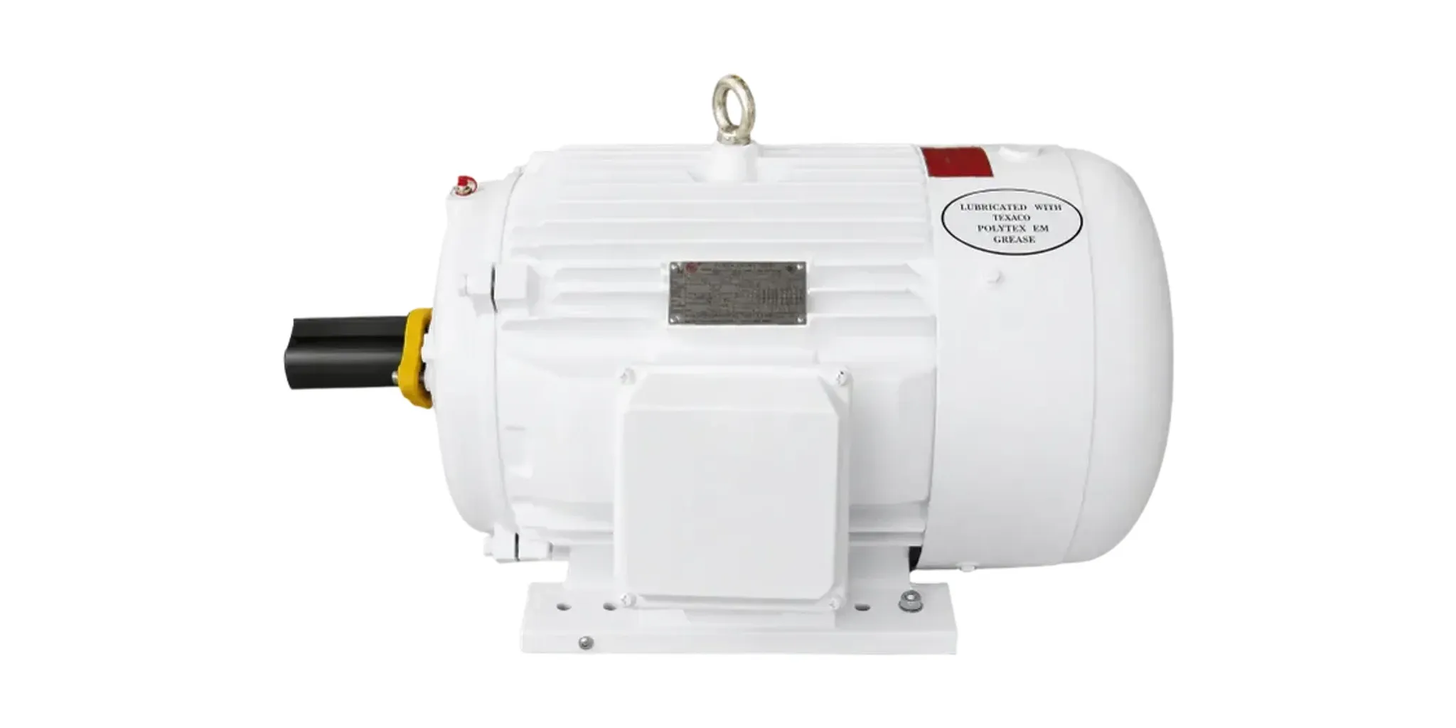
Search oil well pump motors and you get product listings. What almost nobody writes down is why the listings are full of a motor design you will not find on a conveyor, a fan or a pump anywhere else in the plant.
Direct answer
A beam pumping unit is not a steady load. Torque requirements vary widely across the production pumping cycle, and there are two peaks in every stroke: one when the sucker-rod string and the fluid column are lifted, and one when the counterweight is lifted.
A motor meets a torque peak in one of two ways. It can hold speed and draw more current, or it can give up speed and draw less. Which one it does is set by its rated slip — and rated slip is precisely what NEMA’s motor designs differ on.
NEMA Design D is defined at a slip at rated load of 5% or more. Designs A, B, BE, C and CE are each defined at less than 5%. That single number is why the oilfield has its own motor design.
What the standard actually says
ANSI/NEMA MG 1-2024 defines Design D in 1.19.1.6 as a squirrel-cage motor that:
- withstands full-voltage starting;
- develops high locked-rotor torque per 12.38;
- draws locked-rotor current no greater than the limits in 12.35.2 (60 Hz) or 12.35.4 (50 Hz);
- has a slip at rated load of 5% or more.
Clause 12.38.3 puts a number on the torque: for single-speed polyphase squirrel-cage medium motors rated 150 horsepower and smaller, 4-, 6- or 8-pole, at rated voltage and frequency, locked-rotor torque shall be not less than 275% of full-load torque.
Read those two requirements together and the machine’s character follows. High locked-rotor torque means it can break a loaded pumping unit away from standstill. High slip means that when the polished rod load arrives, the rotor slows a little and the peak is absorbed as a speed excursion rather than passed straight through to the line as current.
| Design B | Design C | Design D | |
|---|---|---|---|
| Rated slip | Less than 5% | Less than 5% | 5% or more |
| Locked-rotor torque | General-purpose levels | Special high-torque | ≥275% (≤150 hp, 4/6/8-pole) |
| Behaviour at a torque peak | Holds speed, current rises | Holds speed, current rises | Sheds speed, current peak reduced |
| Oilfield pumping duty | Use with care | Where conditions are less severe | The usual specification |
Where Design B goes wrong on a pumping unit
The petroleum engineering literature is specific about this, and the failure mode is worth understanding because it is an economic one, not a mechanical one.
A Design B motor on a pumping unit produces high cyclic current peaks. On a large, stiff supply that may be tolerable. On a small distribution system it is not — and it gets worse when several wells on the same feeder happen to fall into step, so their peaks coincide instead of averaging out.
The second problem is the one that costs money quietly. Because a Design B motor has less starting torque available, the way to make it break away reliably is to fit a bigger one. Now the motor is oversized for the average load, so it runs at a low load factor, and an induction motor at a low load factor has a poor power factor. The well pumps, the bill goes up, and nothing on site looks broken.
Design C sits between the two and is used where the duty is less severe.
The derating nobody puts on the quotation
Here is the part that turns the argument above into a number. A motor on a cyclic load is thermally loaded more heavily than the same average load applied steadily, because horsepower ratings depend on how far temperature rises under load. A machine running a pumping cycle therefore has to be derated from its full-load nameplate rating.
Worse, you cannot see this with ordinary instruments. Heating follows the RMS (thermal) current — the square root of the mean of the squares of the currents over defined intervals — and that figure is always higher than the average input current an ordinary ammeter shows. Reading it takes an RMS or thermal-type ammeter.
The ratio of average horsepower output to the thermal horsepower output corresponding to that RMS current is the motor derating factor, always less than one; its inverse is the cyclic-load factor, always greater than one. Typical averages:
| Design | Average derating factor |
|---|---|
| NEMA C | 0.65 |
| NEMA D | 0.75 |
That is the second reason the oilfield settled on Design D, and it is independent of starting torque: on the same cyclic duty, a Design C machine gives up roughly a third of its nameplate while a Design D gives up a quarter.
Power factor is part of the specification, not an afterthought
Motors for oil-well pumping combine high starting torque with relatively low power factor, and the average load on them is fairly low. Both effects push the same direction, which is why power factor correction is standard practice rather than an upgrade.
And there is a threshold worth knowing, because it is where the cost appears. A NEMA D machine typically runs at a power factor of about 0.87 at full load, falling to roughly 0.76 at half load — while utilities commonly require better than 0.80 to avoid a penalty. So the gap between a correctly sized motor and an oversized one is not a gradual efficiency drift; it is the difference between sitting above the penalty threshold and sitting below it. As a well’s fluid volume declines, a motor that was correct at completion can cross that line without anything appearing to change.
Where the capacitors go depends on what else is wrong:
- At the individual motors, switched with them — when the distribution system needs its voltage drop corrected as well as its power factor.
- Banked at the distribution centre — when only power factor needs correcting and the bank is the cheaper installation.
Double and triple-rated motors
There is a class of machine built specifically for this duty: totally enclosed fan-cooled Design D motors that can be reconnected for two or three horsepower ratings at a common speed, usually 1,200 r/min. Published typical ratings are 20/15/10 hp and 50/40/30 hp.
The point is field flexibility. A well’s production declines; the rating that was right at completion is not the rating that is right five years later. A multi-rated motor lets the field select the horsepower at which the machine runs most efficiently for the well as it is now, and change pumping speed by changing the motor sheave and reconnecting — rather than by procuring a different motor.
Two site conditions that decide more than the motor does
Single-phase supply. Where only single-phase power reaches the lease, the recommendation in the literature is to use a single-phase to three-phase converter and a three-phase motor, rather than a large single-phase capacitor-start machine. Two reasons: the large single-phase motor is relatively expensive, and it contains a starting switch that is a source of trouble — both because it can fail and because it is a switch operating in the vicinity of a well where flammable gas may be present. That second reason is a hazardous-area argument, not a reliability argument, and it is the one that should settle it.
Control. Packaged oil-well control units exist for exactly this application: a weatherproof enclosure containing a combination magnetic starter, a time switch that starts and stops the motor on a program, a timing relay that delays the restart after a power failure, and lightning arresters. The timing relay matters more than it looks — without it, every well on a feeder restarts simultaneously after an outage.
What this means when you are buying
Four questions, in this order. Only the last one is about the motor.
- What is the load shape? Conventional beam unit, long-stroke unit, or progressing cavity pump — these are different problems, not different sizes of the same problem.
- What is the peak torque, and how often does it arrive? Strokes per minute sets the duty; polished rod load sets the peak.
- What is the supply? Voltage, phases, and how stiff the feeder is. This decides whether cyclic current peaks are a nuisance or a real constraint, and whether you need correction capacitors at the motor or at the bank.
- Which design, and at what slip? With the first three answered, this one is close to determined.
LEADGO’s NEMA Design D series is built for this duty in NEMA T-frames 213T to 449T, 3 to 150 hp, at a rated slip of 5% or more, with CSA certification covering Class I, Division 2, Groups A, B, C and D on the certified models. Check the certificate against your own area classification rather than the family-level statement — hazardous-location coverage is granted per model and rating.
Going deeper
- How to size a motor for a beam pump — the three-step load calculation, and the belt-drive versus direct-coupled decision that sits on top of the design choice above
- Permanent magnet vs induction motors in oilfield duty — when the answer is not an induction motor at all
- What TEFC actually means — the enclosure specification that appears alongside the design letter, and why neither implies the other